Positive electrode of solar cell
A technology of solar cells and positive electrodes, applied in the field of solar cells, can solve the problems of reducing the conversion efficiency of solar cells, large surface line loss, large shading loss, etc., and achieve the effects of ensuring service life, reducing loss, and good electrical conductivity.
- Summary
- Abstract
- Description
- Claims
- Application Information
AI Technical Summary
Problems solved by technology
Method used
Image
Examples
Embodiment 1
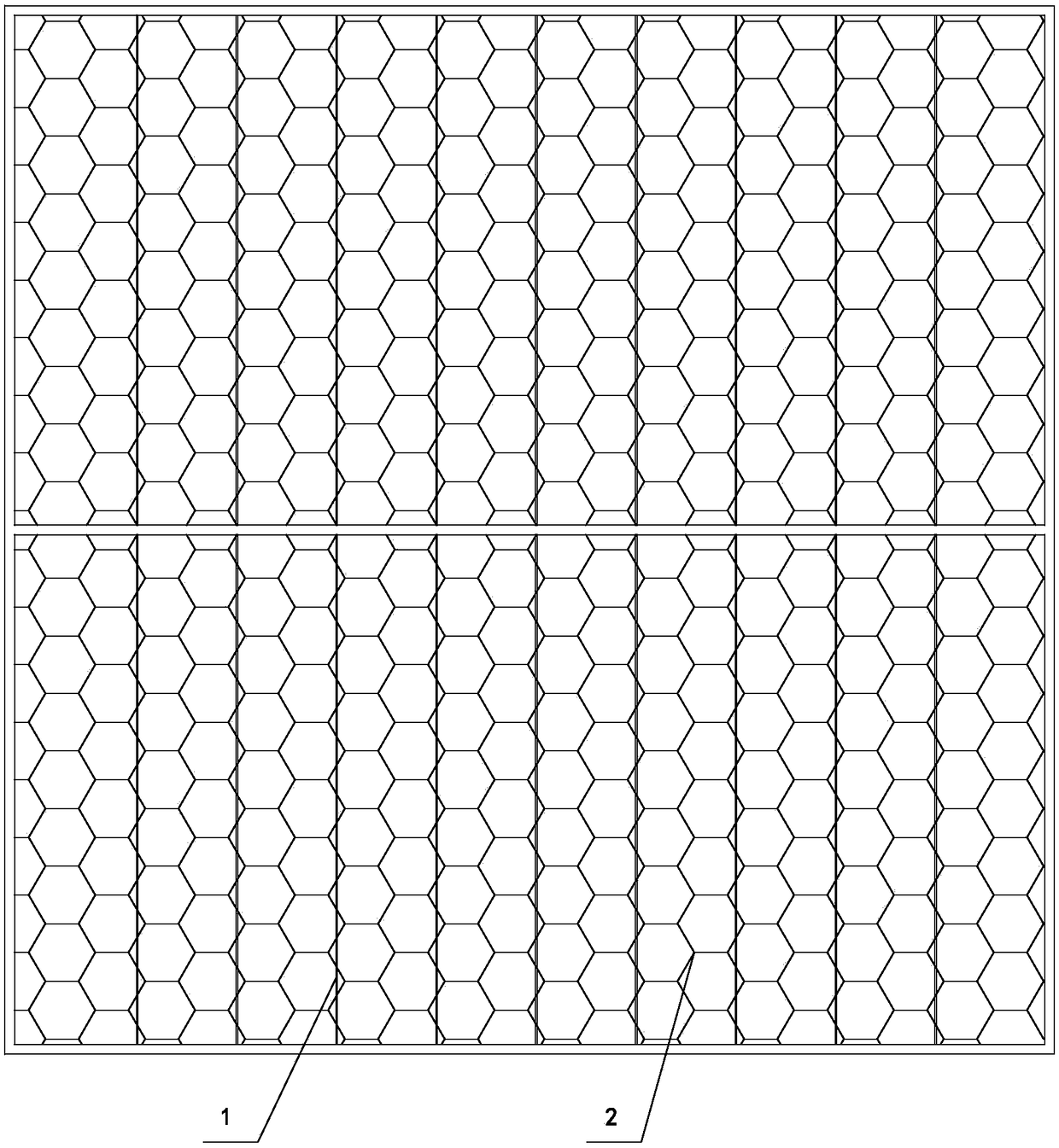
[0023] Depend on figure 1 It can be seen from the schematic diagram of the structure of the positive electrode of the solar cell of the present invention that it includes busbars 1 arranged in parallel and fine grids 2 arranged in a hexagonal honeycomb shape. The conductive capability of the resistor can be adjusted according to the requirement of grid line density to shrink or stretch, and there is an overlapping part between the main grid line 1 and the thin grid line 2 .
[0024] Seen from the vertical state of the busbar 1 , the hexagonal number of the thin gridlines 2 matched with the busbar 1 ranges from 1 to 3 columns. In this embodiment, the number of hexagons of the thin grid lines 2 matched with one bus bar 1 is 2, and the hexagons of the bus bar 1 and one row of the thin grid lines 2 are overlapped and combined. From figure 1 It can be seen from the figure that the main grid lines are overlapped and combined with the hexagonal fine grid lines in the second column....
Embodiment 2
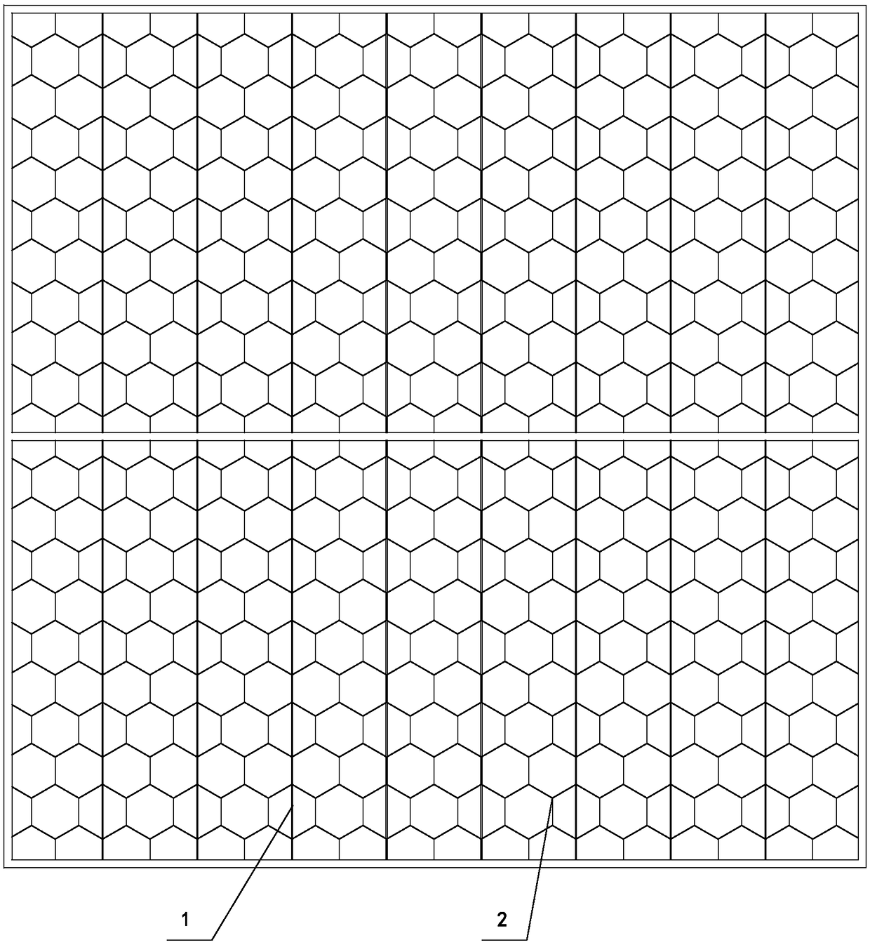
[0028] Depend on figure 2 It can be seen from the schematic diagram of the structure of the positive electrode of the solar cell of the present invention that it includes busbars 1 arranged in parallel and fine grids 2 arranged in a hexagonal honeycomb shape. The conductive capability of the resistor can be adjusted according to the requirement of grid line density to shrink or stretch, and there is an overlapping part between the main grid line 1 and the thin grid line 2 .
[0029] Seen from the vertical state of the busbar 1 , the hexagonal number of the thin gridlines 2 matched with the busbar 1 ranges from 1 to 3 columns. In this embodiment, the number of hexagons of the thin grid lines 2 matched with one bus bar 1 is 2, and the hexagons of the bus bar 1 and one row of the thin grid lines 2 are overlapped and combined. From figure 1 It can be seen from the figure that the main grid lines are overlapped and combined with the hexagonal fine grid lines in the second column...
Embodiment 3
[0033] Depend on image 3 It can be seen from the schematic diagram of the structure of the positive electrode of the solar cell of the present invention that it includes busbars 1 arranged in parallel and fine grids 2 arranged in a hexagonal honeycomb shape. The conductive capability of the resistor can be adjusted according to the requirement of grid line density to shrink or stretch, and there is an overlapping part between the main grid line 1 and the thin grid line 2 .
[0034] Seen from the vertical state of the busbar 1 , the hexagonal number of the thin gridlines 2 matched with the busbar 1 ranges from 1 to 3 columns. In this embodiment, the number of hexagons of the thin grid lines 2 matched with one bus bar 1 is 2, and the hexagons of the bus bar 1 and one row of the thin grid lines 2 are overlapped and combined. From figure 1 It can be seen from the figure that the main grid lines are overlapped and combined with the hexagonal fine grid lines in the second column....
PUM
 Abstract
Description
Claims
Application Information
 - R&D
- Intellectual Property
- Life Sciences
- Materials
- Tech Scout
- Unparalleled Data Quality
- Higher Quality Content
- 60% Fewer Hallucinations
Browse by: Latest US Patents, China's latest patents, Technical Efficacy Thesaurus, Application Domain, Technology Topic, Popular Technical Reports.
© 2025 PatSnap. All rights reserved.Legal|Privacy policy|Modern Slavery Act Transparency Statement|Sitemap|About US| Contact US: help@patsnap.com


