
A graphene-based resonant controller

A resonant controller and graphene technology, applied in antennas, electrical components, etc., can solve problems such as a single direction of electromagnetic wave electric field polarization direction

Active Publication Date: 2020-11-03
HARBIN UNIV OF SCI & TECH
View PDF6 Cites 0 Cited by
  • Summary
  • Abstract
  • Description
  • Claims
  • Application Information

AI Technical Summary

Problems solved by technology

[0008] The present invention is to solve the problem that the electric field polarization direction of the electromagnetic wave is a single direction when the light-dark mode coupling EIT structure based on graphene is used. The present invention provides a graphene-based resonant controller

Method used


Image

  • A graphene-based resonant controller
  • A graphene-based resonant controller
  • A graphene-based resonant controller

Examples


specific Embodiment approach 1

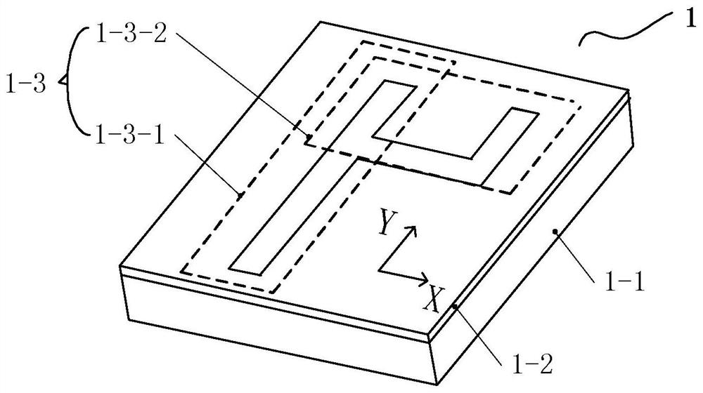
[0029] Specific implementation mode one: see figure 1 Describe this embodiment, this embodiment is a graphene-based resonance controller, including a rectangular resonance controller composed of a plurality of tunable resonance units 1;

[0030] The tunable resonant unit 1 is a rectangular structure, and from bottom to top are rectangular silicon substrate 1-1, SiO 2 Coating 1-2 and resonance ring 1-3;

[0031] The resonant ring 1-3 includes No. 1 graphene nanoribbon 1-3-1 and No. 2 graphene nanoribbon 1-3-2, No. 1 graphene nanoribbon 1-3-1 as a bright mode or dark mode resonator, No. 2 graphene nanoribbon 1-3-2 is used as a bright mode or dark mode resonator, and the modes of No. 1 graphene nanoribbon 1-3-1 and No. 2 graphene nanoribbon 1-3-2 are different;

[0032] No. 1 graphene nanoribbon 1-3-1 is a long strip structure, No. 2 graphene nanoribbon 1-3-2 is a U-shaped ring structure, a part of the long strip structure overlaps with a side wall of the U-shaped ring structur...

specific Embodiment approach 2

[0036] Specific implementation mode two: seefigure 1 Describe this embodiment, the difference between this embodiment and the graphene-based resonant controller described in Embodiment 1 is that the U-shaped ring structure includes two vertical nanobelts and a horizontal nanobelt; The belt is linear.

specific Embodiment approach 3

[0037] Specific implementation mode three: see figure 1 Describe this embodiment, the difference between this embodiment and the graphene-based resonant controller described in the second embodiment is that a vertical nanoribbon of U-shaped ring structure and No. 1 graphene nanometer strip structure With 1-3-1 coaxial.


PUM

PropertyMeasurementUnit
thicknessaaaaaaaaaa
thicknessaaaaaaaaaa
thicknessaaaaaaaaaa

Abstract

The invention provides a grapheme based resonance controller and relates to the field of group delay adjustable controllers. The invention solves a problem that an electric field polarization direction of electromagnetic waves is single when a grapheme based light-shade mode is coupled to an EIT structure. The controller includes a rectangular resonance controller composed of a plurality of adjustable resonance units. Each adjustable resonance unit has a rectangular structure and is composed of a rectangular silicon substrate, a SiO2 coating and a resonance ring arranged from bottom up in sequence. Each resonance ring includes a No.1 grapheme nanometer band and a No.2 grapheme nanometer band, wherein the No.1 grapheme nanometer band has a long strip shaped structure while the No.2 graphemenanometer band has a U shaped ring structure and one part of the long strip shaped structure overlaps with one side wall of the U shaped ring structure and said part and said side wall are coplanar.The resonance rings are used for realizing energy coupling between the No.1 grapheme nanometer bands and No.2 grapheme nanometer bands under electromagnetic induction, so that electromagnetically induced transparency with adjustable window frequency of the resonance adjustable resonance units is generated. The controller provided by the invention is mainly used for storage of optical signals.

Description

technical field [0001] The invention relates to the field of adjustable group delay controllers. Background technique [0002] Electromagnetic induced transparency (EIT) was first discovered in a three-level atomic system and has received extensive attention. The so-called electromagnetically induced transparency, in the original definition, is regarded as a medium that can strongly absorb light of a certain frequency, and when another beam that can be absorbed by the medium is added, the medium no longer absorbs the first beam of light , but a transparent peak phenomenon for light transmission appears. In addition to the corresponding changes in the absorption and dispersion properties of the medium, the electromagnetically induced transparency also slows down the group velocity of light at the peak of transparency, that is, slows down the propagation speed of the optical signal in the medium, and can coherently transform the light with high intensity Stored on media, the...

Claims


Application Information

Patent Timeline
Patent Type & Authority Patents(China)
IPC IPC(8): H01Q15/00
CPCH01Q15/0026H01Q15/0066
Inventor 梅金硕
Owner HARBIN UNIV OF SCI & TECH
Learn More