
Symmetrical 4-degree of freedom series-parallel hybrid antenna structure system

A technology of antenna structure and degree of freedom, applied in the direction of antenna, antenna support/installation device, electrical components, etc., can solve the problems of many driving motors and unsuitable types, achieve continuous tracking, expand the scope of application, and realize continuous tracking Effect

Pending Publication Date: 2018-12-04
NO 54 INST OF CHINA ELECTRONICS SCI & TECH GRP
View PDF0 Cites 4 Cited by
  • Summary
  • Abstract
  • Description
  • Claims
  • Application Information

AI Technical Summary

Problems solved by technology

[0005] In view of the many shortcomings of the traditional antenna and the six-degree-of-freedom parallel mechanism mentioned above, a symmetrical four-degree-of-freedom hybrid antenna structure system is provided, which solves the problem of the "blind area" of the traditional antenna seat over the top, and realizes the antenna work At the same time as the continuous tracking of any attitude in the airspace without blind spots, it also solves the shortcomings of the six-degree-of-freedom parallel mechanism antenna mount that requires more drive motors and cannot be applied to antennas other than circular polarization, and expands the parallel mechanism antenna mount The scope of application of the rack

Method used


Image

  • Symmetrical 4-degree of freedom series-parallel hybrid antenna structure system
  • Symmetrical 4-degree of freedom series-parallel hybrid antenna structure system
  • Symmetrical 4-degree of freedom series-parallel hybrid antenna structure system

Examples


Embodiment Construction

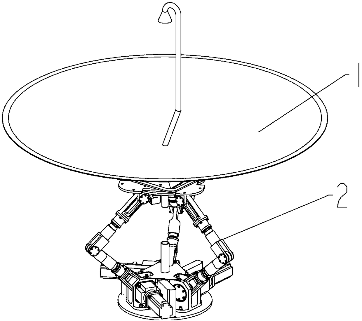
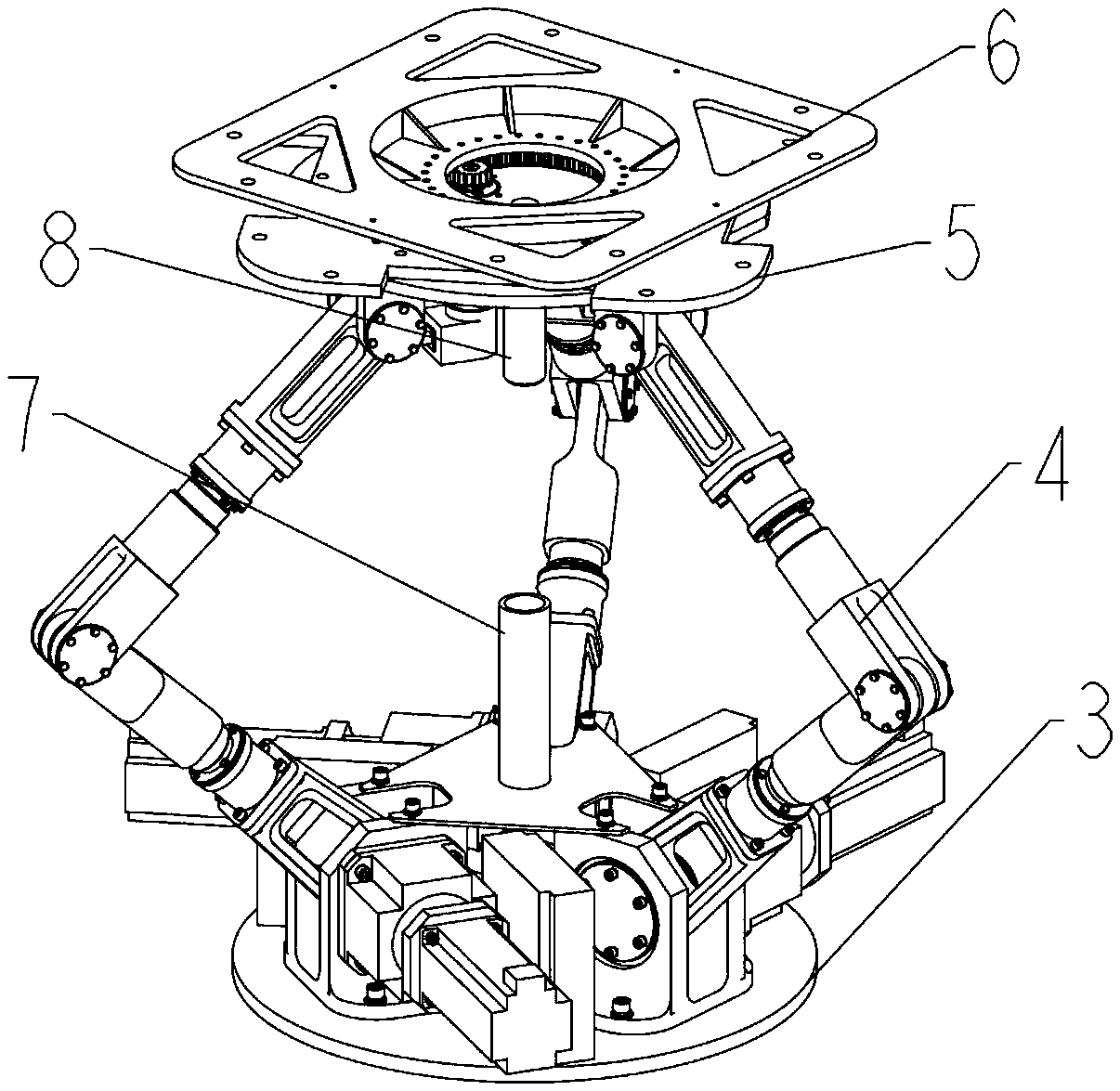
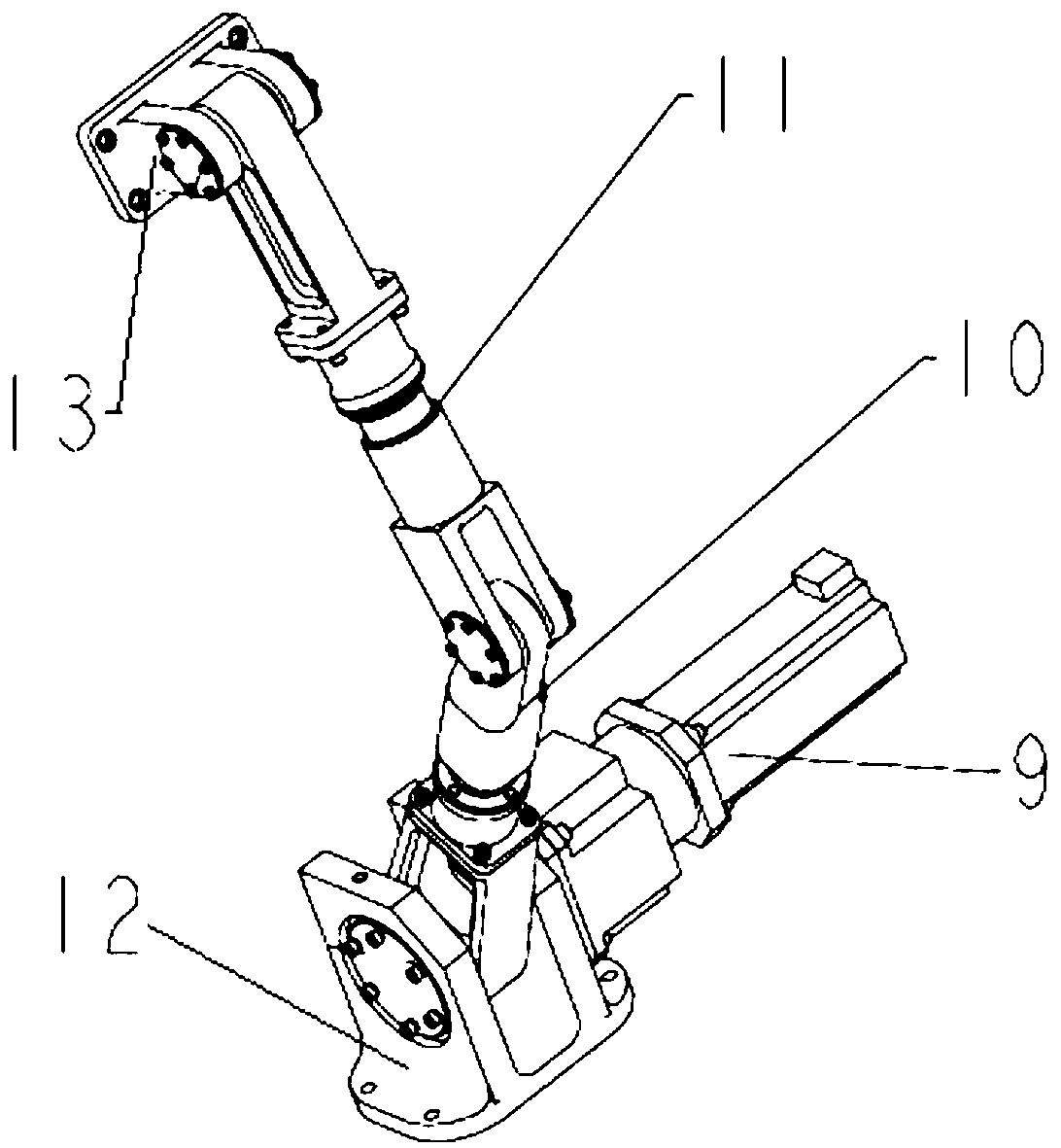
[0028] The invention is described in further detail below in conjunction with accompanying drawing:

[0029] Such as figure 1 , 2 As shown, a symmetrical four-degree-of-freedom hybrid antenna structure system is provided, including an antenna reflector 1, and the antenna reflector 1 is connected to the antenna mount 2, and the antenna mount includes a three-degree-of-freedom parallel connection Mechanism and polarized rotation device, the top of the three-degree-of-freedom parallel mechanism is connected to form a free end that can be driven freely;

[0030] The polarized rotation device includes a polarized plate and a fixed plate 5, the fixed plate is fixed at the free end, the polarized plate is located above the fixed plate, and a rotating bearing is concentrically arranged between the fixed plate and the polarized plate, The polarizing plate is fixedly connected to the inner ring of the rotary bearing, and the fixed plate is fixedly connected to the outer ring of the ro...


PUM


Abstract

The invention discloses a symmetrical 4-degree of freedom series-parallel hybrid antenna structure system, which comprises an antenna reflector. The antenna reflector is connected on an antenna pedestal; a polarization rotation device comprises a polarization plate and a fixing plate; the fixing plate is fixed at the top of the antenna pedestal; the polarization plate is located above the fixing plate; a rotating bearing is concentrically arranged between the fixing plate and the polarization plate; the polarization plate is fixedly connected with the inner ring of the rotating bearing; the fixing plate is fixedly connected with the outer ring of the rotating bearing; the center of the polarization plate extends outwards to form a toothed ring edge; a polarization motor fixed on the fixingplate is matched with the toothed ring edge to drive the polarization plate to rotate in an auto mode; a driving arm and a driven arm are provided with rotating rod shafts; the rotating rod shafts are hinged; the hinged rotating rod shafts generate the ability to rotate in the own circumference during a movement process, and thus, the rotating rod shafts can have rotating energy during use, and the radius of rotation can be improved when rotating directions coincide.

Description

technical field [0001] The invention belongs to the field of antenna devices, and in particular relates to a symmetrical four-degree-of-freedom hybrid antenna structure system. Background technique [0002] The antenna pedestal is the support and orientation device of the antenna system. Its function is to enable the antenna reflector to follow the predetermined trajectory or follow the target movement, accurately point to the target, and accurately measure the direction of the target. Its structure is largely It affects the performance index of the whole antenna. [0003] With the rapid development of antenna technology, the size and weight of antenna mounts continue to increase, and the performance requirements for rotational angular velocity, angular acceleration, accuracy, stiffness, reliability, and dynamic characteristics are increasing. It is difficult to meet these requirements. With the development of technology, parallel mechanisms have gradually begun to be appl...

Claims


Application Information

Patent Timeline
IPC IPC(8): H01Q3/02H01Q15/24H01Q1/12H01Q19/12
CPCH01Q1/12H01Q3/02H01Q15/24H01Q19/12
Inventor 段艳宾窦玉超侯雨雷付强李建军曾达幸侯荣伟
Owner NO 54 INST OF CHINA ELECTRONICS SCI & TECH GRP
Learn More