
Self-clamping lifting mechanism

A self-clamping and clamping arm technology, applied in the field of production and assembly of new energy vehicle gearbox casings, can solve the problems of narrow application area, high cost, complex structure, etc., and achieve the effect of fast clamping range

Pending Publication Date: 2018-12-04
安徽航科自动化设备有限公司
View PDF0 Cites 4 Cited by
  • Summary
  • Abstract
  • Description
  • Claims
  • Application Information

AI Technical Summary

Problems solved by technology

For the handling and assembly process of the shell, the spreader used is generally designed according to the shape of the shell itself, and the application area is relatively narrow; the structure of the manual spreader is simple and requires manpower to operate the grasping position of the spreader; the structure of the automated spreader is complex, Often contain pneumatic or electric components, high cost

Method used


Image

  • Self-clamping lifting mechanism
  • Self-clamping lifting mechanism
  • Self-clamping lifting mechanism

Examples


Embodiment Construction

[0030] In order to make the technical means, creative features, goals and effects achieved by the present invention easy to understand, the technical solutions in the embodiments of the present invention will be clearly and completely described below in conjunction with the accompanying drawings in the embodiments of the present invention. Obviously, the The described embodiments are only some, not all, embodiments of the present invention. Based on the embodiments of the present invention, all other embodiments obtained by persons of ordinary skill in the art without creative efforts fall within the protection scope of the present invention.

[0031] In the description of the present invention, it should be noted that the orientation or positional relationship indicated by the terms "vertical", "upper", "lower" and "horizontal" are based on the orientation or positional relationship shown in the drawings, and are only for It is convenient to describe the utility and simplify ...


PUM


Abstract

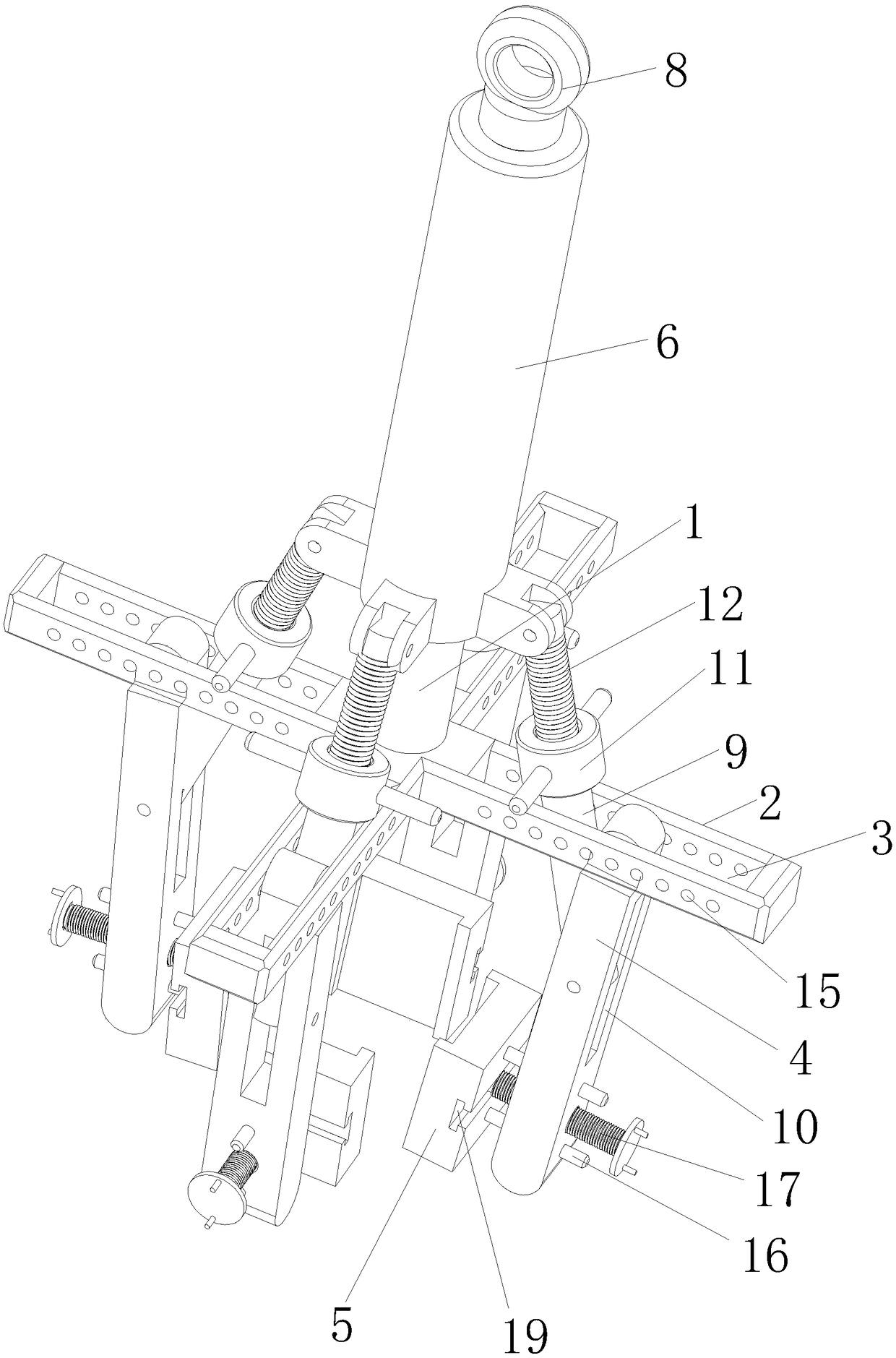
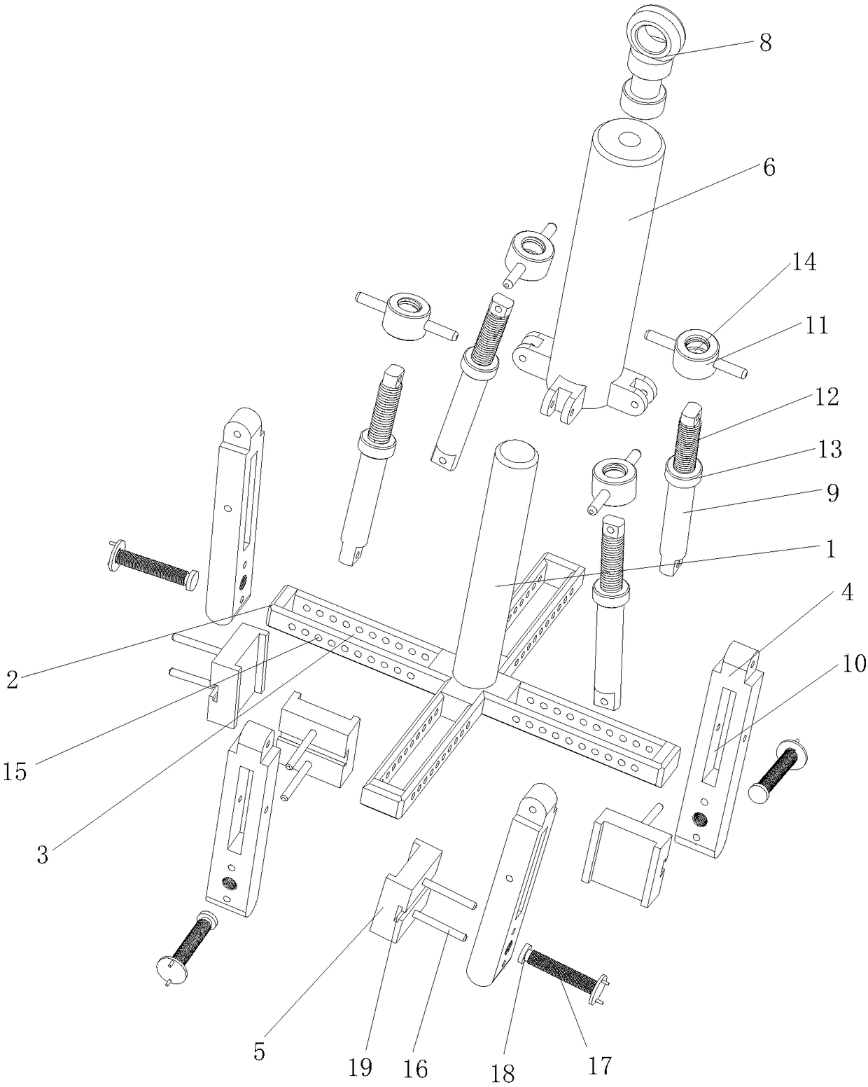
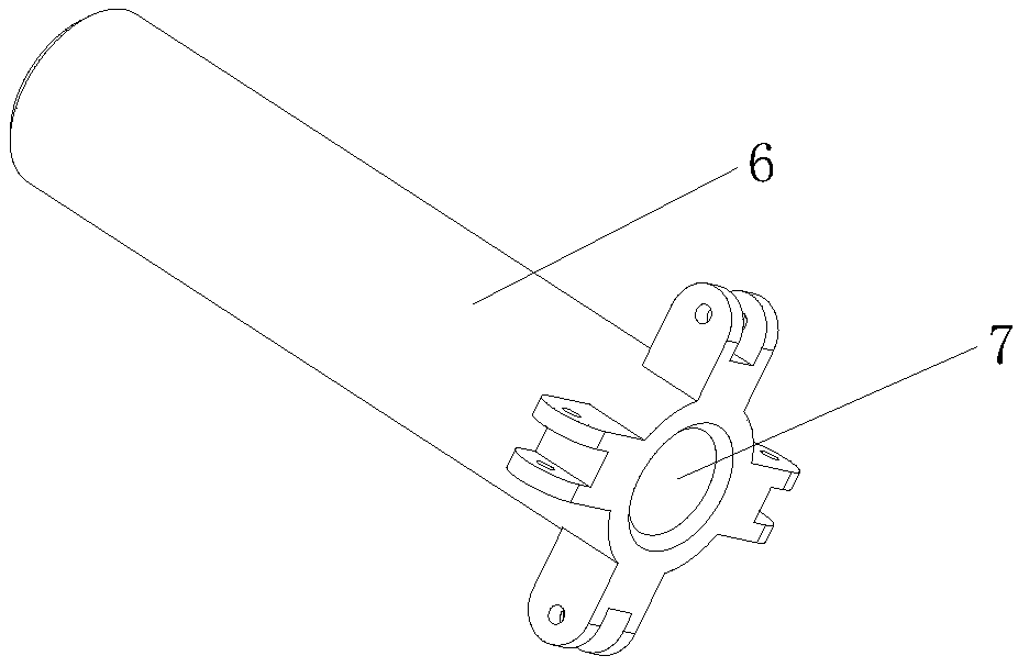
The invention relates to the technical field of production and assembling of a gearbox housing of a new energy automobile, in particular to a self-clamping lifting mechanism comprising a fixed shaft,a bracket, a clamping arm, a clamping claw, a sliding sleeve, a lifting ring, a connecting sleeve, an internal thread rotating sleeve, and a screw rod. The bracket is arranged at the bottom of the fixed shaft; and a chute is formed in the bracket. The clamping arm is hinged to the chute; and the clamping claw is connected to the clamping arm. According to the invention, an external device hooks the lifting ring and drives the sliding sleeve to slide on the fixed shaft in a sleeving manner; the screw rod is dragged to drive the clamping arm to rotate along a hinge part with the bracket, therebyrealizing clamping and thus realizing automatic clamping during the lifting process. With the internal thread rotating sleeve, the screw rod, and the connecting sleeve, the internal thread rotating sleeve rotates to drive the screw rod in threaded connection to move along the axial direction of the connecting sleeve, thereby realizing adjustment of the clamping force of the clamping arm; and withthe adjusting mechanism, adaptability to lifting of gearbox housings with different sizes is enhanced.

Description

technical field [0001] The invention relates to the technical field of production and assembly of new energy vehicle gearbox housings, in particular to a self-clamping lifting mechanism. Background technique [0002] Today, the shapes of gearbox housings for new energy vehicles vary widely. For the handling and assembly process of the shell, the spreader used is generally designed according to the shape of the shell itself, and the application area is relatively narrow; the structure of the manual spreader is simple and requires manpower to operate the grasping position of the spreader; the structure of the automated spreader is complex, Often contain pneumatic or electric components, the cost is high. Contents of the invention [0003] The purpose of the present invention is to overcome the problems existing in the prior art, and provide a self-clamping lifting mechanism, which can realize automatic clamping during lifting, adjustable clamping stroke, and adjustable clam...

Claims


Application Information

Patent Timeline
Patent Type & Authority Applications(China)
IPC IPC(8): B66C1/44
CPCB66C1/44
Inventor 李海
Owner 安徽航科自动化设备有限公司
Learn More