Eureka AIR delivers breakthrough ideas for toughest innovation challenges, trusted by R&D personnel around the world.

Three-dimensional elliptical ultrasonic vibration cutting device adopting longitudinal bending composite mode

A technology of ultrasonic vibration cutting and compound mode, which is applied in the direction of fluid using vibration, can solve problems such as difficult-to-machine materials and parts with weak rigidity, and achieve the effects of less adjustment links, improved power output capability, and convenient processing and assembly

Inactive Publication Date: 2018-12-04
ZHENGZHOU AIRCRAFT EQUIP
View PDF5 Cites 23 Cited by
  • Summary
  • Abstract
  • Description
  • Claims
  • Application Information

AI Technical Summary

Problems solved by technology

[0005] The purpose of the present invention is to provide a three-dimensional elliptical ultrasonic vibration cutting device with longitudinal bending composite mode in order to solve the cutting problems of various difficult-to-machine materials, weak rigidity parts and parts with free-form surfaces in the fields of aerospace and military industry

Method used


Image

  • Three-dimensional elliptical ultrasonic vibration cutting device adopting longitudinal bending composite mode
  • Three-dimensional elliptical ultrasonic vibration cutting device adopting longitudinal bending composite mode
  • Three-dimensional elliptical ultrasonic vibration cutting device adopting longitudinal bending composite mode

Examples


Embodiment Construction

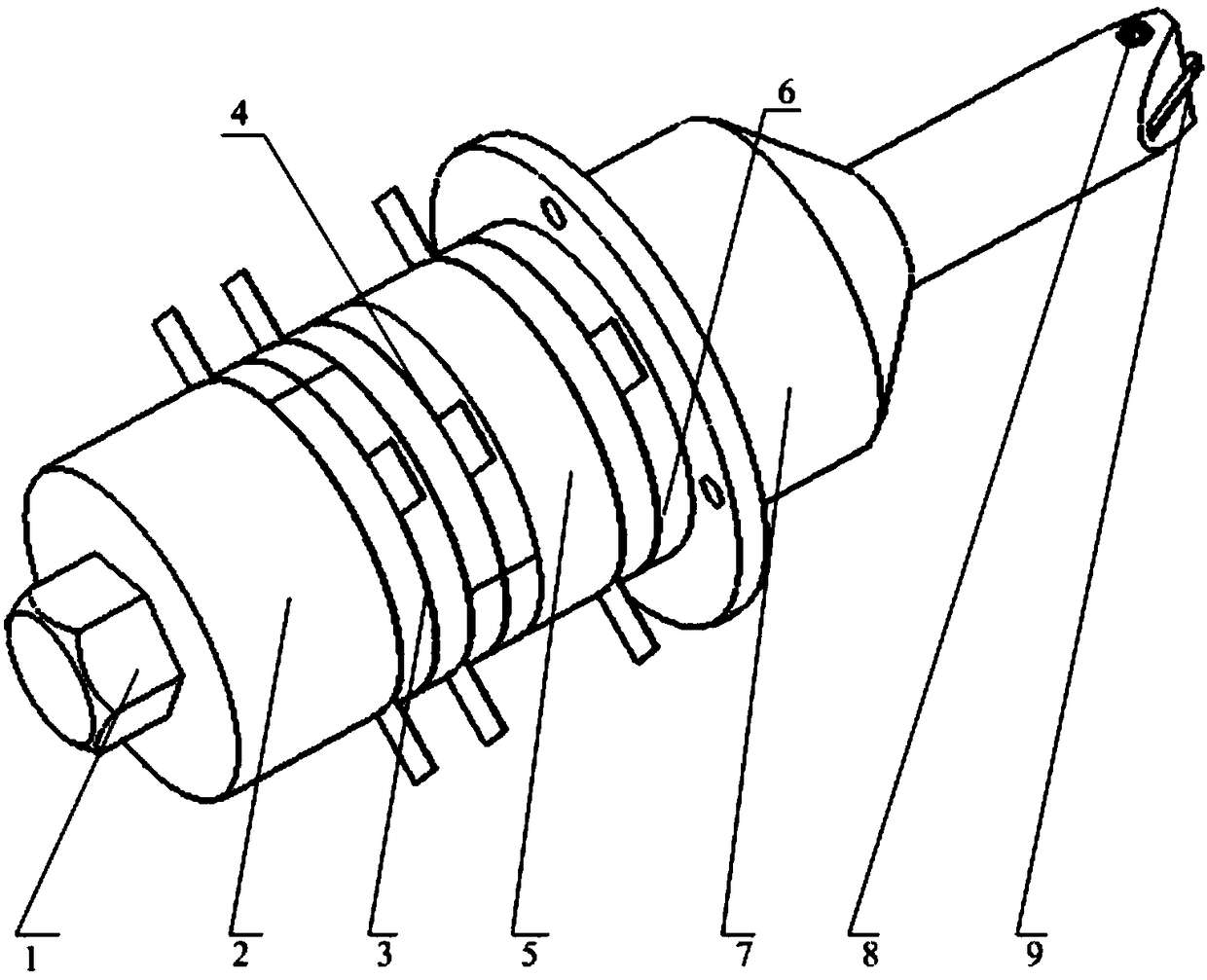
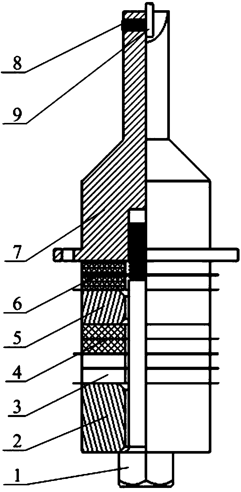
[0032] see figure 1 , Figure 1A , Figure 1B As shown, a longitudinal bending compound mode three-dimensional ultrasonic vibration assisted cutting device of the present invention, the cutting device includes a fastening bolt 1, a rear cover plate 2, a first excitation source 3, a second excitation source 4, a middle cover Plate 5, the third excitation source 6 and the flanged front cover 7; the structures of the rear cover 2 and the middle cover 5 are both hollow cylinder structures; 7 in the sipe 76. After the threaded section of the fastening bolt 1 passes through the rear cover plate 2, the first excitation source 3, the second excitation source 4, the middle cover plate 5 and the third excitation source 6, it is threaded on the flanged front cover plate 7. B threaded hole 73, so that the rear cover 2, the first excitation source 3, the second excitation source 4, the middle cover 5, the third excitation source 6 and the front cover 7 are fastened together; the tool ca...


PUM


Abstract

The invention discloses a three-dimensional elliptical ultrasonic vibration cutting device adopting a longitudinal bending composite mode. The three-dimensional elliptical ultrasonic vibration cuttingdevice is composed of a pre-tightening bolt, a rear cover plate, a first excitation source, a second excitation source, a middle cover plate, a third excitation source and a flange front cover plate.The three-way excitation sources are driven by input signals with the same frequency, wherein the phase angles of the input signal are different in pairs. By adjusting the voltage and phase difference of driving signals of the three-way excitation sources, a tool nose point of a tool mounted at the output end of the three-dimensional elliptical ultrasonic vibration cutting device obtains spatialelliptic vibration trajectories with different vibration amplitudes and phase differences. According to the three-dimensional elliptical ultrasonic vibration cutting device, the assembly link is less,and mounting and dismounting of a blade are convenient; a flange structure is adopted, and the system stiffness is good; and the effect on the aspect of cutting machining of parts with hard machiningmaterials, weak stiffness and free curved surfaces is remarkable, cutting force and the cutting temperature can be significantly decreased, tool abrasion and machining deformation of the workpiece materials can be significantly reduced, the surface quality and form and position accuracy of the parts are improved, the subsequent machining process is reduced, and then the machining efficiency and economical efficiency are improved.

Description

technical field [0001] The invention relates to a processing device for difficult-to-machine materials, weak-rigidity parts and parts with free-form surfaces in precision ultra-precision machining, in particular to a three-dimensional elliptical ultrasonic vibration cutting device in longitudinal and bending composite mode. Background technique [0002] Two-dimensional elliptical ultrasonic vibration cutting is a processing method first proposed by Japanese scholars in 1993. The research results of scholars at home and abroad show that two-dimensional elliptical ultrasonic vibration cutting can suppress cutting chatter, reduce cutting force and cutting temperature, reduce tool wear, improve machining accuracy and surface quality, and realize ductile cutting of brittle materials. The processing of difficult-to-machine materials such as alloys, composite materials and ceramics, as well as weak rigidity parts such as slender shafts and thin-walled parts has significant advantag...

Claims


Application Information

Patent Timeline
IPC IPC(8): B23D79/00B06B1/06
Inventor 胡林华张蔚峰刘家旺刘生峰
Owner ZHENGZHOU AIRCRAFT EQUIP
Why Eureka
Eureka Blog
Learn More