Time synchronization method, device and system
A time-synchronized and asynchronous technology, applied in time-division multiplexing systems, electrical components, multiplexing communications, etc., to solve the problems of difficulty in popularizing smart devices and high usage costs
- Summary
- Abstract
- Description
- Claims
- Application Information
AI Technical Summary
Problems solved by technology
Method used
Image

Examples
Embodiment 1
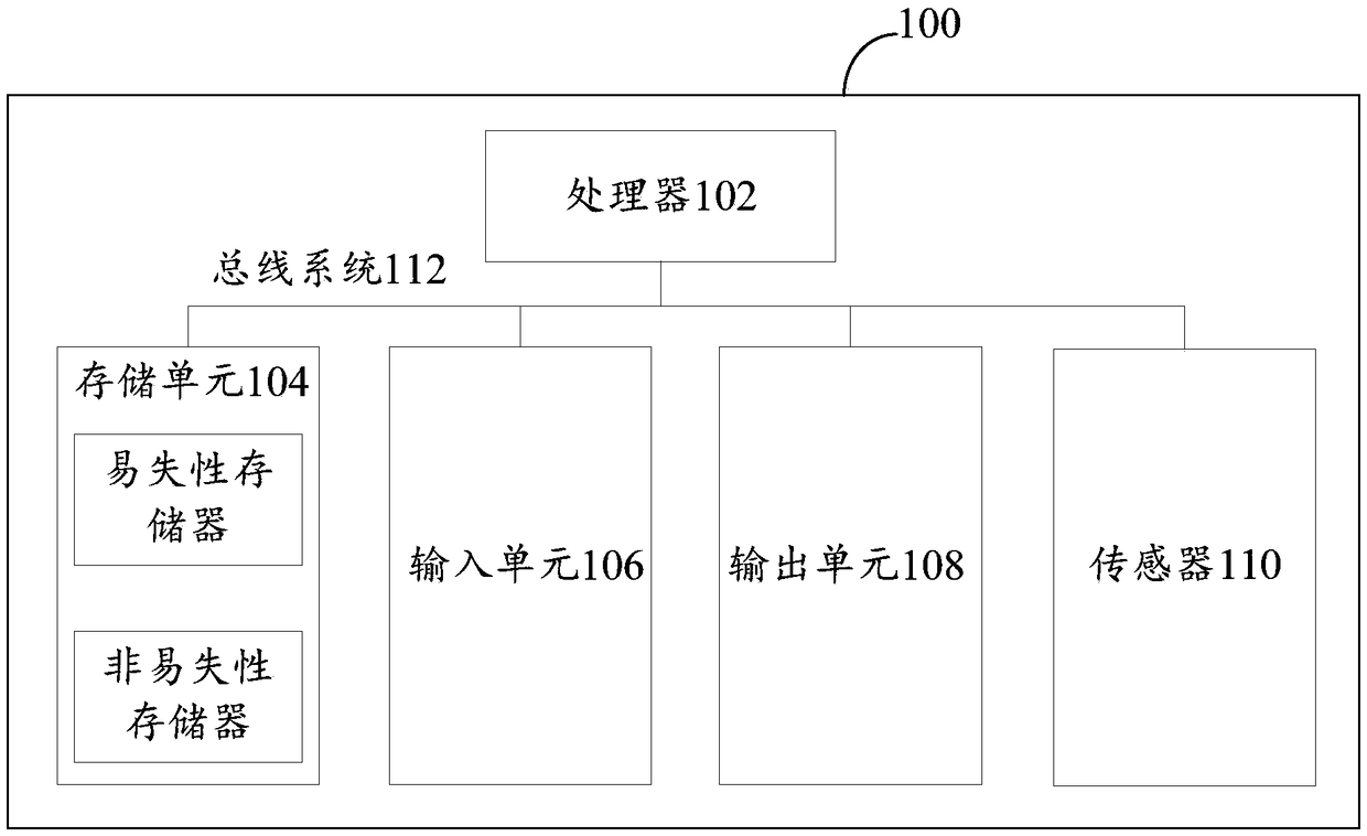
[0034] First, refer to figure 1 An example electronic device 100 for implementing the time synchronization method, device and system of the embodiments of the present invention will be described.
[0035] Such as figure 1 Shown is a schematic structural diagram of an electronic device, the electronic device 100 includes one or more processors 102, one or more storage devices 104, an input device 106 and an output device 108, these components are connected via a bus system 112 and / or other forms interconnected by a connecting mechanism (not shown). It should be noted that figure 1 The components and structure of the electronic device 100 shown are only exemplary, not limiting, and the electronic device may also have other components and structures as required.
[0036] The processor 102 can be implemented in at least one hardware form of a digital signal processor (DSP), a field programmable gate array (FPGA), and a programmable logic array (PLA), and the processor 102 can b...
Embodiment 2
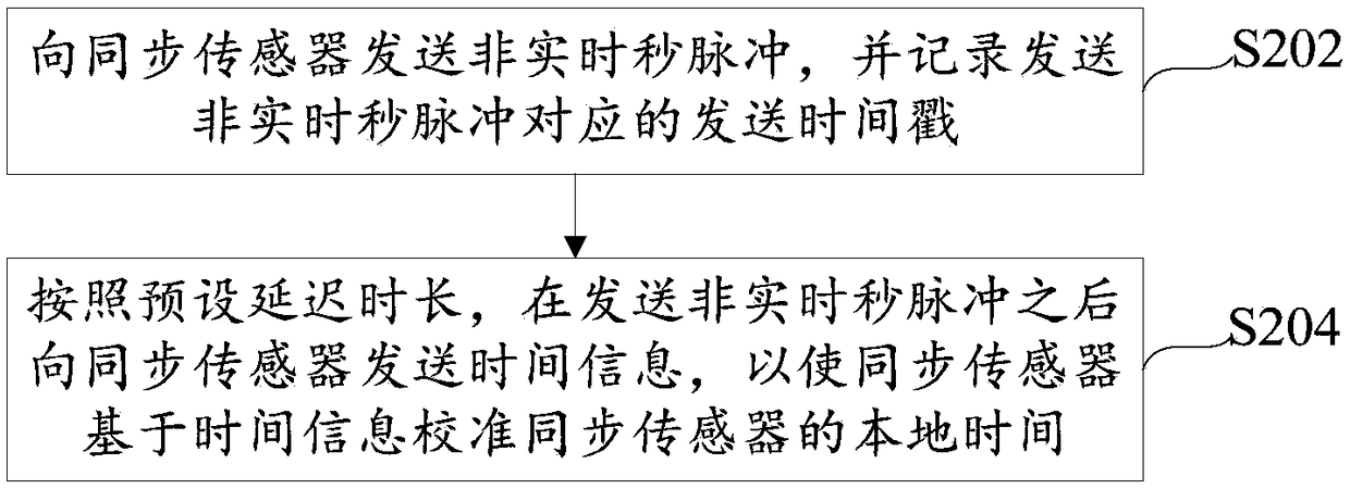
[0043] refer to figure 2 A flow chart of a time synchronization method is shown, the method is executed by a controller, and the controller is connected with at least one synchronization sensor. A synchronous sensor is a sensor that needs to be synchronized with the controller. The delay time of this type of sensor is usually not fixed, so it is necessary to adopt a time synchronization method to keep this type of sensor and the controller in time synchronization, such as figure 2 As shown, it specifically includes the following steps:
[0044] Step S202, sending the non-real-time second pulse to the synchronous sensor, and recording the sending time stamp corresponding to the non-real-time second pulse; wherein, the time difference between two adjacent sending time stamps is an indeterminate value.
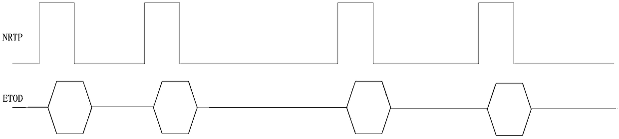
[0045] For the simplicity of description, the non-real-time second pulse can be referred to as NRTP (Not Real Time Pulse) below. The pulse sent by the controller to the synchr...
Embodiment 3
[0067] refer to Figure 4 A flow chart of a time synchronization method is shown, the method is executed by a synchronous sensor, the synchronous sensor is a sensor that needs to be synchronized with the controller, the synchronous sensor is connected to the controller, and the method includes:
[0068] Step S402, receiving the non-real-time pulse second sent by the controller, and using the local time of the synchronous sensor to record the arrival time stamp corresponding to the non-real-time pulse second. Since the pulses sent by the controller are not real-time pulses, the time interval between two adjacent pulses is not fixed, and the time interval between two adjacent non-real-time second pulses received by the synchronous sensor is not a fixed value.
[0069] Step S404, receiving the time information sent by the controller; wherein, the time information includes the sending time stamp of the non-real-time pulse second. Since the time information sent by the controller ...
PUM
 Abstract
Description
Claims
Application Information
 - R&D
- Intellectual Property
- Life Sciences
- Materials
- Tech Scout
- Unparalleled Data Quality
- Higher Quality Content
- 60% Fewer Hallucinations
Browse by: Latest US Patents, China's latest patents, Technical Efficacy Thesaurus, Application Domain, Technology Topic, Popular Technical Reports.
© 2025 PatSnap. All rights reserved.Legal|Privacy policy|Modern Slavery Act Transparency Statement|Sitemap|About US| Contact US: help@patsnap.com