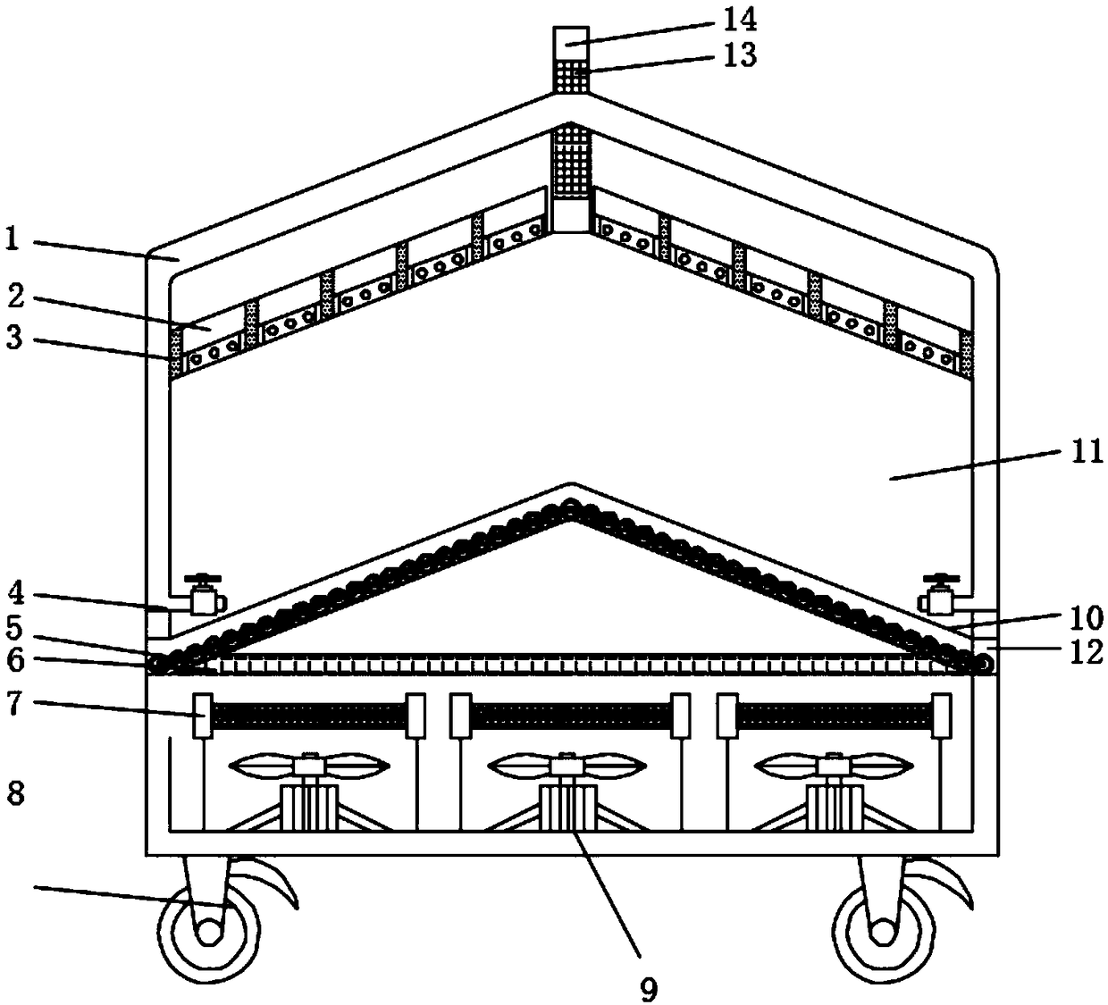
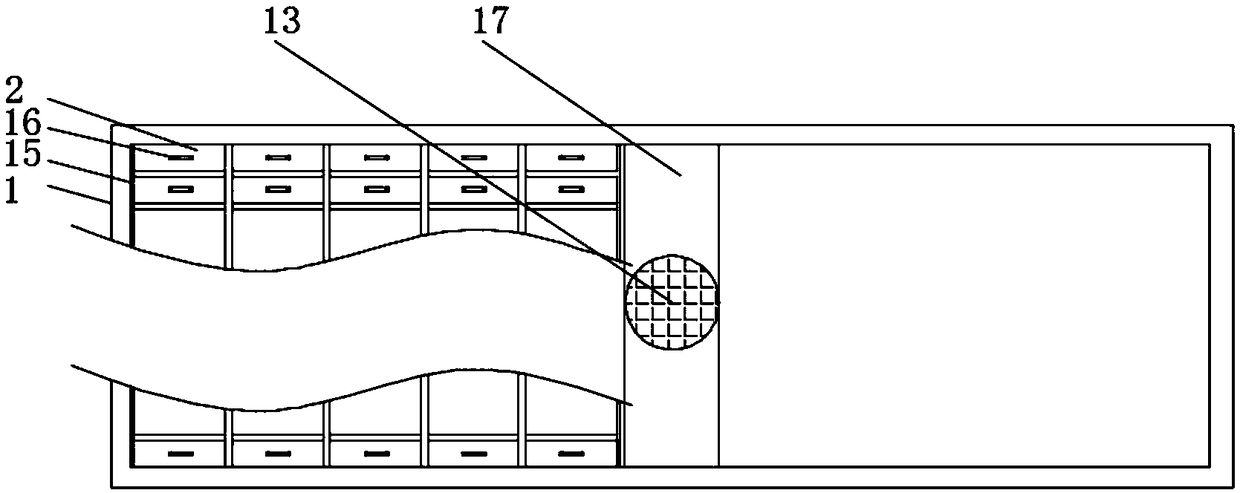
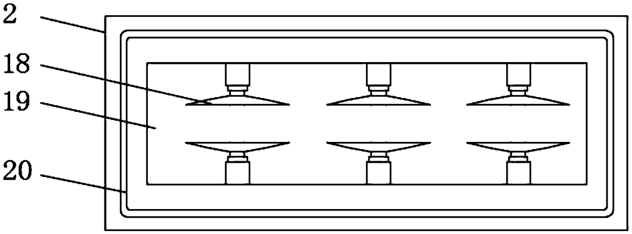
Automatic drying board for PCB boards

A technology of PCB board and drying device, which is applied in drying, drying machine, drying gas arrangement and other directions, can solve the problems of uneven direct heating temperature, affect economic benefits, affect work efficiency, etc., and improve work efficiency and quality. The effect of guaranteeing, reducing the output of personnel wages, and improving the recycling rate

Inactive Publication Date: 2018-11-30
黄永锋
View PDF0 Cites 0 Cited by
  • Summary
  • Abstract
  • Description
  • Claims
  • Application Information

AI Technical Summary

Problems solved by technology

[0003] The PCB board needs to be washed, dust-removed and dried during the board-making process. The existing drying equipment uses the method of directly heating the PCB board to remove moisture. Due to the uneven temperature of the direct heating, the deformation and degumming of the PCB board are irreparable. The damage will affect the economic benefits. Long-term drying will cause the steam in the drying box to increase and cannot be eliminated, which will affect the drying efficiency. When the drying equipment continues to work, the drying material rate will weaken accordingly, and a large amount of drying cannot be continuously performed. , affect the drying efficiency, a large amount of toxic and odorous gas will be produced during the drying process, the staff working in such an environment for a long time will affect the health of the staff, and will bring negative emotions to the staff and affect the work efficiency and Drying quality of PCB board

Method used


Image

  • Automatic drying board for PCB boards
  • Automatic drying board for PCB boards
  • Automatic drying board for PCB boards

Examples


Embodiment Construction

[0017] The following will clearly and completely describe the technical solutions in the embodiments of the present invention with reference to the accompanying drawings in the embodiments of the present invention. Obviously, the described embodiments are only some, not all, embodiments of the present invention. Based on the embodiments of the present invention, all other embodiments obtained by persons of ordinary skill in the art without making creative efforts belong to the protection scope of the present invention.

[0018] In the description of the present invention, it should be noted that the terms "center", "upper", "lower", "left", "right", "vertical", "horizontal", "inner", "outer" etc. The indicated orientation or positional relationship is based on the orientation or positional relationship shown in the drawings, and is only for the convenience of describing the present invention and simplifying the description, rather than indicating or implying that the referred d...


PUM


Abstract

The invention discloses an automatic drying board for PCB boards. The device comprises a drying box and object placing boards. A drying bin is arranged in the interior of the drying box. The top of the drying bin is equipped with the object placing boards. Middle positions at tops of the object placing boards are provided with pull handles. Additionally, separation grooves are arranged around thebottoms of the object placing boards. Clamp grooves are arranged in the interiors of the object placing boards. Additionally, sucking discs are arranged in the interiors of the clamp grooves. Protrusion sealing strips are welded around the bottoms of the object placing boards. Additionally, bottoms of the protrusion sealing strips are clamped into fixing grooves. The PCB boards are clamped betweenthe sucking discs arranged in the interiors of the object placing boards. The sucking discs absorb the PCB boards. Through the pull handles, the object placing boards are placed on the upper surfacesof the grooves. The PCB boards stretch into the drying bin for drying. When the PCB boards reach the drying requirement, the sucking discs are separated from the PCB boards. The PCB boards drop downon sliding rollers and slide out of a board outlet. The multiple object placing boards are used for drying a large number of PCB boards. Therefore, the drying amount of PCB boards is increased. Accordingly, working efficiency is increased.

Description

technical field [0001] The invention relates to the technical field of auxiliary production devices for PCB boards, in particular to an automatic drying device for PCB boards. Background technique [0002] The printed circuit board is a PCB circuit board, also known as a printed circuit board. It is a provider of electrical connections for electronic components. Its development has a history of more than 100 years. Its design is mainly layout design. The main advantages of using circuit boards It greatly reduces wiring and assembly errors, improves automation level and production labor rate, and can be divided into single-panel, double-panel, four-layer board, six-layer board and other multi-layer circuit boards according to the number of circuit board layers. In the production process of the PCB board, it is necessary to carry out timely and effective drying operations on the PCB board, so as to reduce the relative humidity of the PCB board itself and improve the processing...

Claims


Application Information

Patent Timeline
Patent Type & Authority Applications(China)
IPC IPC(8): F26B15/02F26B21/02F26B25/02
CPCF26B15/02F26B21/001F26B21/02F26B25/02
Inventor 黄永锋
Owner 黄永锋
Why Eureka
Try Eureka