
Spiral blade centrifugal fan

A centrifugal fan and helical blade technology, applied in the field of centrifugal fan and helical blade centrifugal fan, can solve the problems of axial length limitation, large pressure loss and low efficiency of ordinary centrifugal fans.

Inactive Publication Date: 2018-11-30
大连碧蓝节能环保科技有限公司
View PDF6 Cites 0 Cited by
  • Summary
  • Abstract
  • Description
  • Claims
  • Application Information

AI Technical Summary

Problems solved by technology

[0006] The purpose of the present invention is to overcome the disadvantages of large pressure loss and low efficiency of ordinary cross-flow fans, as well as the limitation of the axial length of ordinary centrifugal fans, and provide a fan with unrestricted axial length and relatively high output airflow pressure. , high efficiency spiral blade centrifugal fan

Method used


Image

  • Spiral blade centrifugal fan
  • Spiral blade centrifugal fan
  • Spiral blade centrifugal fan

Examples


Embodiment Construction

[0037] The present invention is further described below in conjunction with accompanying drawing.

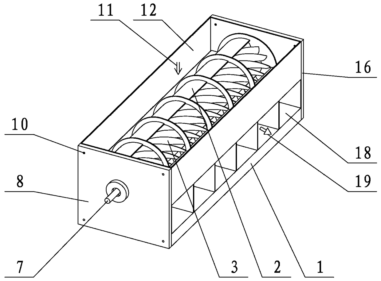
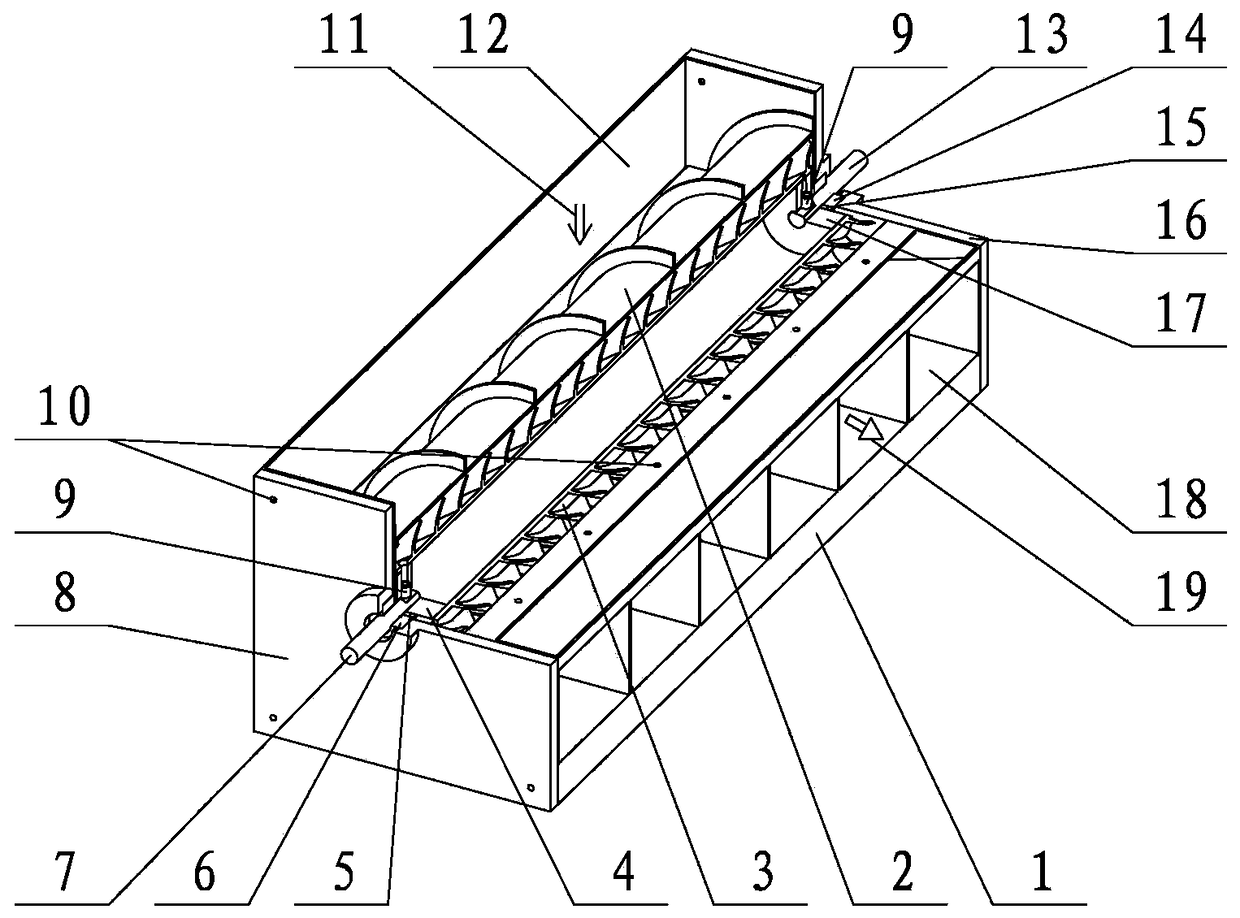
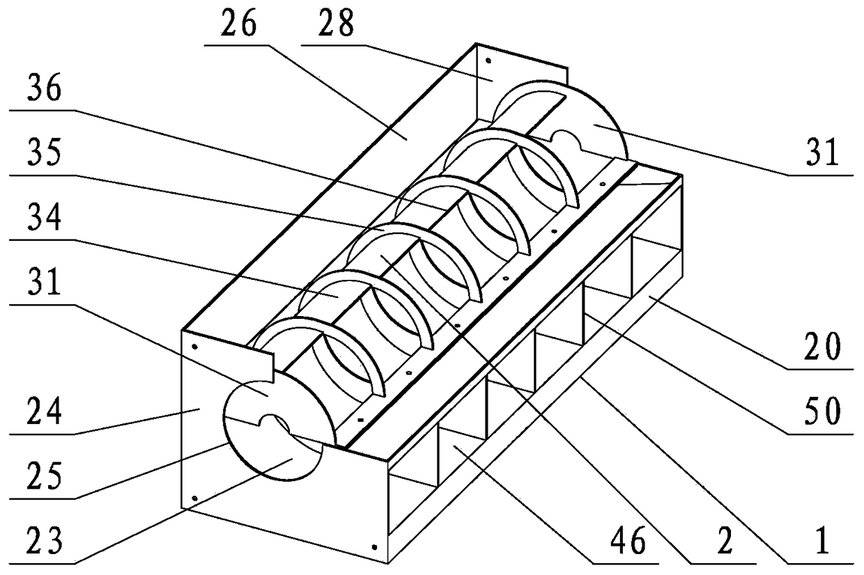
[0038] refer to figure 1 , figure 2 , Figure 12 , Figure 15 , The centrifugal fan includes a base part, a guide volute 2, and an impeller part. The guide volute 2 is installed in the inner cavity of the base part, the impeller part is installed in the inner cavity of the guide volute 2, and the motor is installed in one axial end of the base part. When the centrifugal fan is in operation, the motor drives the impeller 3 of the impeller part to rotate. Under the action of centrifugal force, the airflow is accelerated during the process of flowing along the helical impeller channel 40 of the impeller 3, and the airflow in the impeller channel 40 flows from the guide When the front end 36 of the flow volute plate enters the inner cavity of the guide volute 2, the cross-sectional area of ​​the volute cavity 46 on the radially inner side of the guide volute 2 and the volute pl...


PUM


Abstract

The invention provides a spiral blade centrifugal fan and in particular relates to a centrifugal fan. The spiral blade centrifugal fan comprises an engine base part, a flow guide volute and an impeller part. When the centrifugal fan is operated, a motor drives impellers to rotate; airflow is accelerated under the action of a centrifugal force when the airflow flows along a spiral impeller flow channel of the impellers; when the airflow in the impeller flow channel enters an inner cavity of the flow guide volute from the front end of a flow guide volute plate, the section area of the inner cavity of the volute at the radial inner sides of the flow guide volute and a volute plate of the engine base is gradually increased; the airflow is decelerated and pressurized in the inner cavity of thevolute and kinetic energy which is transmitted to the airflow through the impellers is transformed into potential energy to generate high-pressure airflow. The spiral impeller flow channel is arrangedso that an air inlet of the centrifugal fan is distributed along the radial direction of the centrifugal fan, and the airflow flow of the air inlet can be increased by sufficiently utilizing negativepressure which is partially generated through the impeller flow channel; the airflow is continuously and stably conveyed. The centrifugal fan has the advantages that the axial length is not limited,the pressure of output airflow is relatively great and the efficiency is relatively high.

Description

technical field [0001] The invention relates to a helical blade centrifugal fan, which relates to a centrifugal fan, in particular to a centrifugal fan with helical blades and unlimited axial length. Background technique [0002] The types of fans commonly used in home appliances include axial fans, cross-flow fans, and centrifugal fans. Its typical application product examples are vertical fans using axial fans, range hoods using centrifugal fans, and indoor units of air conditioners using cross-flow fans. Axial flow fans are characterized by large flow, low pressure, and high noise. The structure of the axial flow fan is simple. [0003] The cross-flow fan is characterized by moderate flow, moderate pressure and low noise. The axial length of the cross-flow fan is not limited, and the airflow at the air outlet is evenly distributed along the axial direction of the cross-flow fan. Compared with the axial flow fan, the airflow of the cross-flow fan flows through the impe...

Claims


Application Information

Patent Timeline
Patent Type & Authority Applications(China)
IPC IPC(8): F04D17/06F04D25/08F04D29/28F04D29/30F04D29/42F04D29/44F04D29/62
Inventor 赵晓东
Owner 大连碧蓝节能环保科技有限公司
Learn More