
Baffle suitable for outer edge dehumidification and application method thereof

A technology of outer edge and baffle, applied in the direction of engine components, machines/engines, mechanical equipment, etc., can solve the problems of fast steam flow and large steam leakage, so as to improve efficiency, reduce steam flow speed, and ensure water drainage Effect

Pending Publication Date: 2018-11-30
中国船舶重工集团公司第七0三研究所
View PDF12 Cites 0 Cited by
  • Summary
  • Abstract
  • Description
  • Claims
  • Application Information

AI Technical Summary

Problems solved by technology

[0004] The purpose of the baffle structure of the present invention is to solve the problems of fast steam flow and large steam leakage caused by the dehumidification of the outer edge in the prior art, and propose a new type of baffle to adapt to the dehumidification of the outer edge, thereby improving the efficiency of the steam turbine stage and operational safety

Method used


Image

  • Baffle suitable for outer edge dehumidification and application method thereof
  • Baffle suitable for outer edge dehumidification and application method thereof
  • Baffle suitable for outer edge dehumidification and application method thereof

Examples


specific Embodiment approach 1

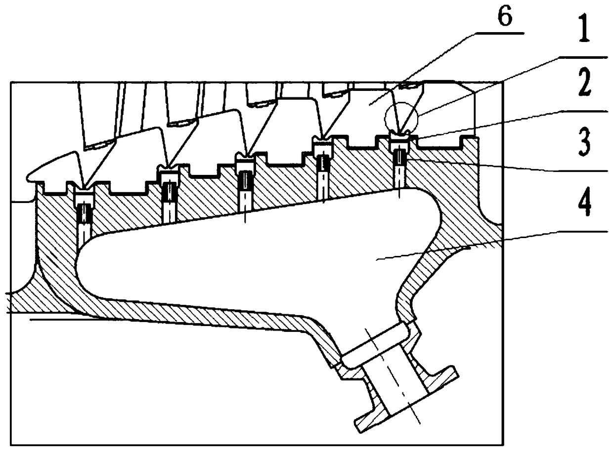
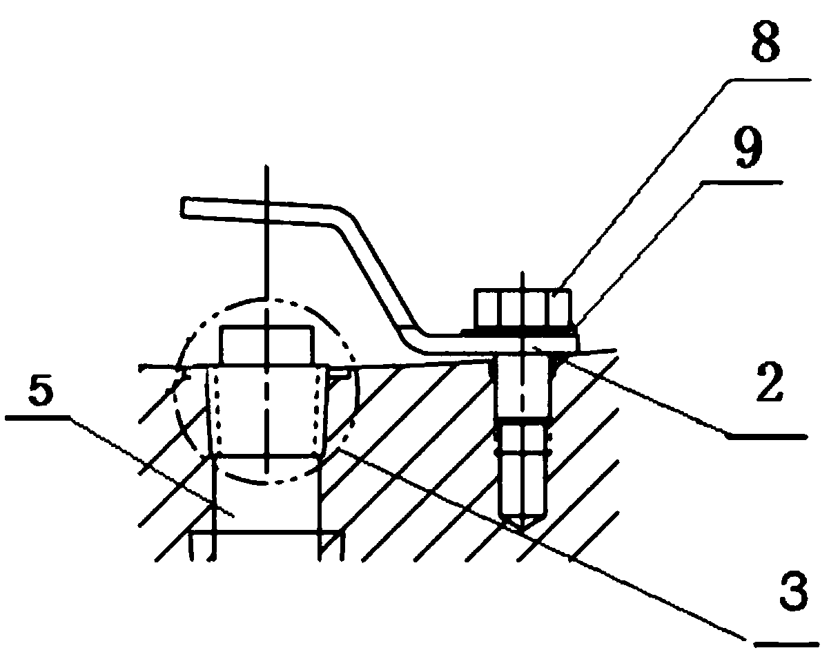
[0026] Specific implementation mode one: combine Figures 1 to 3 Describe this embodiment, a baffle adapted to dehumidification on the outer edge of this embodiment, which includes a baffle 2, a drain valve 3 and a drain chamber 4;

[0027] The upper end of the hydrophobic chamber 4 is opened with a plurality of threaded through holes 5, and the upper surface of the hydrophobic chamber 4 is an inclined plane;

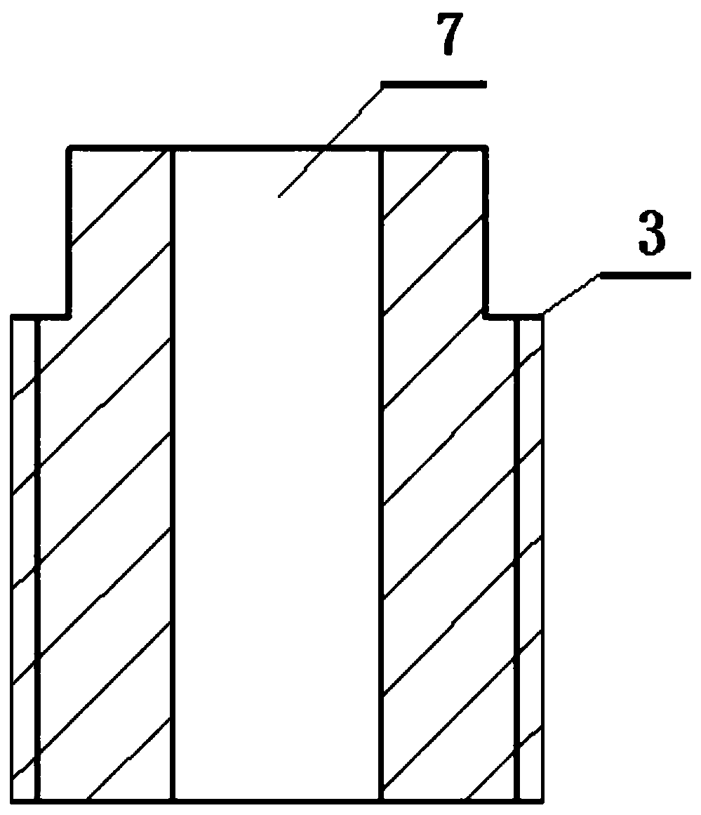
[0028] A through hole 7 is provided in the middle of the steam trap 3, and an external thread is provided on the outer wall; the steam trap 3 is threadedly connected with the threaded through hole 5;

[0029] The baffle 2 has a "Z" shape structure, the end surface of one side of the baffle 2 is attached to the upper surface of the hydrophobic chamber 4, and the baffle 2 is fixed on the hydrophobic chamber 4 by bolts 8; the other side of the baffle 2 is located on the hydrophobic chamber 4. above valve 3.

specific Embodiment approach 2

[0030] Specific implementation mode two: combination Figures 1 to 3 Describe this embodiment, the difference between this embodiment and specific embodiment 1 is: a plurality of blades 6 of the last few stages are respectively arranged on the upper surface of the hydrophobic chamber 4 on the left and right sides of the threaded through hole 5; An outer edge dehumidification zone 1 is formed between the outer edges of the blades 6 .

[0031] Other compositions and connection methods are the same as those in Embodiment 1.

specific Embodiment approach 3

[0032] Specific implementation mode three: combination Figures 1 to 3 This embodiment is described. The difference between this embodiment and the first embodiment is that the outer edge dehumidification zone 1 is located above the baffle plate 2 .

[0033] Other compositions and connection methods are the same as those in Embodiment 1.


PUM


Abstract

The invention provides a baffle suitable for outer edge dehumidification and an application method thereof, and relate to the baffle suitable for outer edge dehumidification and the application methodthereof. The baffle and the application method aim to solve the problems that in the prior art, due to outer edge dehumidification, the steam flow speed is high and the steam leakage amount is large.The baffle structure suitable for outer edge dehumidification and the application method thereof are provided. The baffle is in threaded connection with a cylinder, so that the stage efficiency and the operation safety of a unit are improved. The pressure of a small cavity formed by each level of baffle structure communicates with a hydrophobic cavity and is throat pressure of a condenser, the pressure of an outer edge dehumidification part of a steam turbine is gradually decreased, but the last stage of pressure is also much larger than the pressure of the hydrophobic chamber, and the pressure difference prevents excessive steam in the operation process, so that the work capacity of the steam turbine is improved, and the efficiency of the unit is improved. Due to splashing of water drops, blades are damaged to a certain degree, and the novel baffle structure plays a role in protecting the blades and improving the operation safety of the steam turbine. The baffle is applied to the field of steam turbines.

Description

technical field [0001] The invention relates to the technical field of internal dehumidification structures of steam turbines, in particular to a baffle suitable for dehumidification at the outer edge and a use method thereof. Background technique [0002] In the steam turbine, the slightly superheated or saturated steam expands and does work. After passing through the saturation line, water droplets will condense and precipitate to increase the humidity of the water vapor. If the humidity in the steam turbine is too high and no measures are taken, the blades of the last stages will be eroded, and will be damaged or even broken after working for several years; if the humidity is too high, the blades will corrode rapidly, and dehumidification measures must be taken; Having humidity also makes the unit less efficient. [0003] The outer edge dehumidification technology is often used in the internal dehumidification of nuclear power steam turbines. If the structural design is ...

Claims


Application Information

Patent Timeline
Patent Type & Authority Applications(China)
IPC IPC(8): F01D25/32
CPCF01D25/32
Inventor 郭佳刘统章赵世群李雨薇张红莲李佳冀宁德亮李燕飞
Owner 中国船舶重工集团公司第七0三研究所
Learn More