
A combined ocean energy power generation device

A power generation device and a combined technology, which is applied in the direction of ocean energy power generation, hydropower generation, engine components, etc., can solve the problems of poor equipment construction, installation and positioning, and daily maintenance management, low efficiency of energy harvesting operations, and single equipment capacity collection capabilities Low and other problems, achieve the effect of high integration and operation automation, reduce construction and equipment maintenance costs, and simple structure

Active Publication Date: 2020-06-05
GANZHOU GOLD WATER POWER EQUIP CO LTD
View PDF5 Cites 0 Cited by
  • Summary
  • Abstract
  • Description
  • Claims
  • Application Information

AI Technical Summary

Problems solved by technology

[0002] At present, with the development of ocean energy resource utilization technology, the point-absorption ocean energy collection and conversion is mainly realized through traditional rolling generator equipment and piston energy conversion equipment. Although this method can meet the needs of use, it is In actual use, it is found that the contact area between the currently used equipment and the ocean is relatively small, so the ability of a single equipment to collect is low, and when multiple equipments are required to run at the same time, each equipment needs to operate relatively independently, which leads to the failure of the equipment. The construction, installation, positioning, and daily maintenance management are relatively poor, and the density of energy collection operations is relatively low. At the same time, in the operation of marine energy collection, the structure and working position of the equipment cannot be flexibly adjusted according to the needs of use. , which leads to poor matching between the energy collection of the equipment and the state of ocean currents and waves, the low efficiency of energy collection operations and relatively large equipment operation losses, which cannot effectively meet the needs of centralized collection and transformation of marine resources in a large area. , in view of this situation, there is an urgent need to develop a new ocean energy harvesting equipment to meet the needs of actual use

Method used


Image

  • A combined ocean energy power generation device

Examples


Embodiment Construction

[0015] In order to make the technical means, creative features, goals and effects achieved by the present invention easy to understand, the present invention will be further described below in conjunction with specific embodiments.

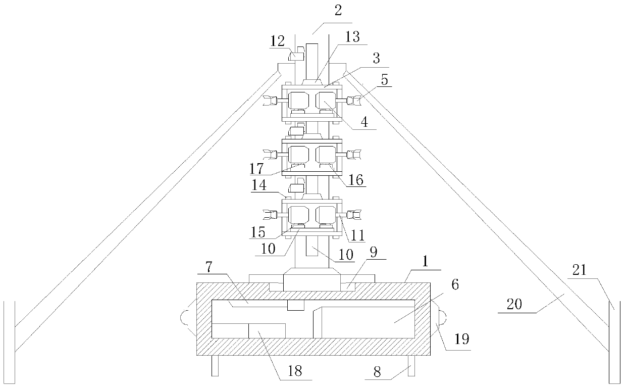
[0016] Such as figure 1 The combined ocean energy power generation device includes a positioning base 1, a bearing column 2, a positioning keel 3, an underwater generator 4, a driving impeller 5, a storage battery pack 6 and a control circuit 7, and the positioning base 1 is a closed cavity Structure, at least two pre-embedded hooks 8 are evenly distributed on the outer surface of the bottom, at least one chute 9 is arranged on the upper surface, the chute 9 is distributed parallel to the upper surface of the positioning base 1, and at least two bearing columns 2 pass through the chute 9 and the positioning The upper surface of the base 1 is slidably connected and distributed vertically with the upper surface of the positioning base 1. At least on...


PUM


Abstract

The invention relates to a combined ocean power generation device. The combined ocean power generation device comprises a positioning base, bearing columns, positioning keels, underwater power generators, driving impellers, a storage battery set and a control circuit, wherein the bearing columns are slidingly connected with the upper surface of the positioning base through sliding grooves, and areperpendicularly distributed on the upper surface of the positioning base; the positioning keels are located between the two adjacent bearing columns, and guiding sliding rails on the side surfaces ofthe positioning keels are slidingly connected with the bearing columns on the two sides; the underwater power generators are embedded into the positioning keels through the guiding sliding rails, andare mutually connected with at least one driving impeller through transmission shafts; both the storage battery set and the control circuit are embedded into the positioning base. The combined oceanpower generation device is simple in structure, flexible and convenient to use and high in universality, integration and automatic running degree, it can be simultaneously met that positive waves, negative waves and ocean current are simultaneously subjected to energy collecting generation operation, the efficiency of collecting, development and utilization work of ocean resources is greatly improved, and the construction and device maintenance cost is reduced.

Description

technical field [0001] The invention relates to an ocean energy collection device, specifically a combined ocean energy power generation device. Background technique [0002] At present, with the development of ocean energy resource utilization technology, the point-absorption ocean energy collection and conversion is mainly realized through traditional rolling generator equipment and piston energy conversion equipment. Although this method can meet the needs of use, it is In actual use, it is found that the contact area between the currently used equipment and the ocean is relatively small, so the ability of a single equipment to collect is low, and when multiple equipments are required to run at the same time, each equipment needs to operate relatively independently, which leads to the failure of the equipment. The construction, installation, positioning, and daily maintenance management are relatively poor, and the density of energy collection operations is relatively low...

Claims


Application Information

Patent Timeline
Patent Type & Authority Patents(China)
IPC IPC(8): F03B13/10F03B13/14
CPCF03B13/10F03B13/14F05B2220/706Y02E10/20Y02E10/30
Inventor 安颖林佳佳曾卫杨希梅
Owner GANZHOU GOLD WATER POWER EQUIP CO LTD
Learn More