
Release structure carried on unmanned aerial vehicle

A technology of unmanned aerial vehicle and connecting mechanism, which is applied in the field of unmanned aerial vehicle, can solve the problems such as the decrease of the carrying capacity of the unmanned aerial vehicle, the influence of the carrying capacity of the unmanned aerial vehicle, and the increase of the load of the unmanned aerial vehicle, so as to achieve the convenient and fast delivery of materials and the structure of the unmanned aerial vehicle. Simple, lightweight effects

Inactive Publication Date: 2018-11-27
陈爱霞
View PDF0 Cites 1 Cited by
  • Summary
  • Abstract
  • Description
  • Claims
  • Application Information

AI Technical Summary

Problems solved by technology

[0002] UAVs can be used to airdrop materials to areas that are inaccessible to ground transportation. At present, no UAV delivery mechanism has yet appeared on the market. If the existing delivery mechanism for other fields is installed on the UAV, due to The structure of this type of delivery mechanism is too complicated, and the overall weight is too large, which will increase the load of the drone, which will seriously affect the load capacity of the drone, and eventually lead to a significant decline in the carrying capacity of the drone, making it impossible to deliver more useful drones. Therefore, it is very necessary to design a drone delivery mechanism with simple structure, light weight, easy control and high reliability

Method used


Image

  • Release structure carried on unmanned aerial vehicle
  • Release structure carried on unmanned aerial vehicle
  • Release structure carried on unmanned aerial vehicle

Examples


Embodiment Construction

[0022] The following will clearly and completely describe the technical solutions in the embodiments of the present invention with reference to the accompanying drawings in the embodiments of the present invention. Obviously, the described embodiments are only part of the embodiments of the present invention, not all of them. Based on the embodiments of the present invention, all other embodiments obtained by persons of ordinary skill in the art without creative efforts fall within the protection scope of the present invention.

[0023] It should be noted that if there is a directional indication (such as up, down, left, right, front, back...) in the embodiment of the present invention, the directional indication is only used to explain the position in a certain posture (as shown in the accompanying drawing). If the specific posture changes, the directional indication will also change accordingly.

[0024] In addition, if there are descriptions involving "first", "second" and ...


PUM


Abstract

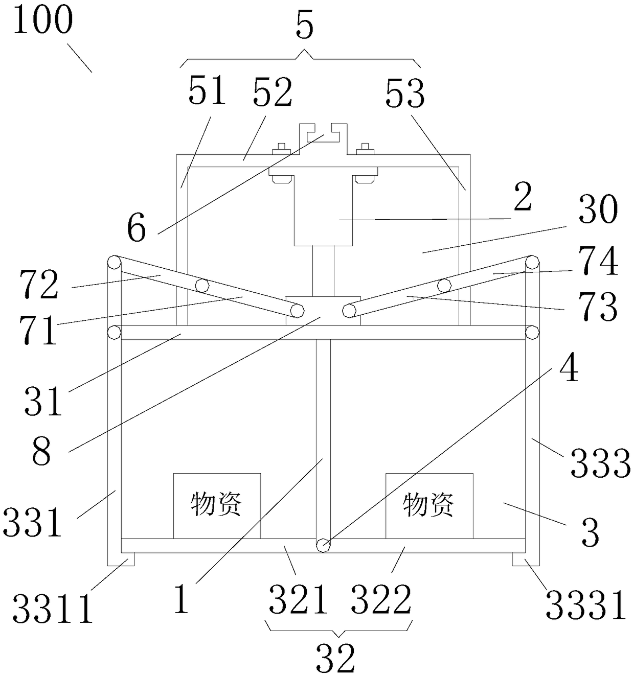
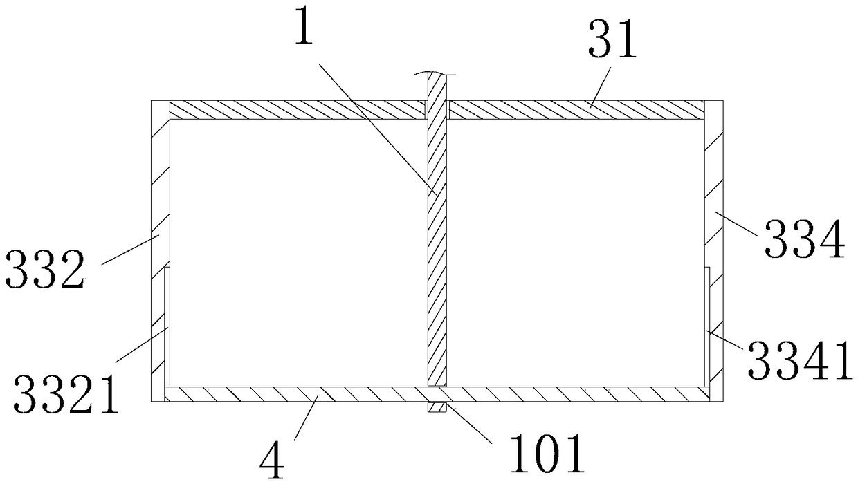
The invention discloses a release structure carried on an unmanned aerial vehicle, and relates to the field of unmanned aerial vehicles. The unmanned aerial vehicle is simple in structure, low in weight, easy to control and high in reliability. According to the adopted technical scheme, the release structure carried on the unmanned aerial vehicle comprises a movable piece, a storage box and a first connecting mechanism, and the first connecting mechanism is used for connecting the storage box to the unmanned aerial vehicle; the storage box comprises a top plate, bottom plates and side plates;the side plates comprise the first side plate, the second side plate, the third side plate and the fourth side plate which are sequentially arranged in the circumferential direction; the bottom platesinclude the first bottom plate and the second bottom plate, one end of the first bottom plate and one end of the second bottom plate are connected through a rotating shaft; the movable piece is connected with the rotating shaft and connected with the first side plate and the third side plate through a second connecting mechanism so as to drive the first bottom plate, the second bottom plate, thefirst side plate and the third side plate to move during movement; the movable piece is used for closing the storage box when moving to the first position and opening the storage box when moving to the second position.

Description

technical field [0001] The invention relates to the technical field of unmanned aerial vehicles, in particular to a delivery structure mounted on an unmanned aerial vehicle. Background technique [0002] UAVs can be used to airdrop materials to areas that are inaccessible to ground transportation. At present, no UAV delivery mechanism has yet appeared on the market. If the existing delivery mechanism for other fields is installed on the UAV, due to The structure of this type of delivery mechanism is too complicated, and the overall weight is too large, which will increase the load of the drone, which will seriously affect the load capacity of the drone, and eventually lead to a significant decline in the carrying capacity of the drone, making it impossible to deliver more useful drones. Therefore, it is very necessary to design a structure-simple, light-weight, easy-to-control, highly reliable UAV delivery mechanism. [0003] Therefore, it is necessary to provide a new tech...

Claims


Application Information

Patent Timeline
IPC IPC(8): B64D1/10B64D1/12
CPCB64D1/10B64D1/12B64U2101/60
Inventor 陈爱霞
Owner 陈爱霞
Learn More