Packing for packed tower and seawater desulfurization device
A technology of desulfurization device and packed tower, applied in chemical/physical process, chemical/physical/physical chemical process, separation method, etc., can solve the problems of high manufacturing cost and large pressure loss, achieve simple structure, inhibit gas Effect of Reduction of Liquid Contact Efficiency
- Summary
- Abstract
- Description
- Claims
- Application Information
AI Technical Summary
Problems solved by technology
Method used
Image
Examples
no. 1 approach
[0049] (The overall structure of the seawater desulfurization device)
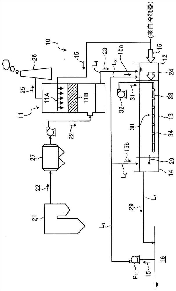
[0050] figure 1 It is a schematic diagram showing the structure of the seawater desulfurization device of the first embodiment. Such as figure 1 As shown, the seawater desulfurization device 10 (desulfurization device) of the first embodiment has a packed tower 11 (exhaust gas desulfurization absorption tower), an inlet side dilution mixing tank 12, an oxidation tank 13 for water quality recovery treatment, and an outlet side dilution mixing tank 14 .
[0051] In this embodiment, the seawater 15 used in the packed tower 11 and the seawater 15 used for water quality improvement in the oxidation tank 13 for water quality recovery treatment are drawn separately and used in the condenser (not shown) of the boiler 21. The seawater before being discharged into the sea 16 after cooling.
[0052] In addition, seawater 15 for dilution is passed through the pump P 11 Via seawater supply line L 1 While drawing ...
no. 2 approach
[0101] Next, a second embodiment will be described. The filler 11Ba of the second embodiment differs from the first embodiment in that the plate portion has a protrusion. In the second embodiment, the description of the same structure as that of the first embodiment is omitted.
[0102] Figure 8 and Figure 9 It is a sectional view of the filling part of 2nd Embodiment. Such as Figure 8 As shown, the first plate unit 64a of the first filling portion 50 of the second embodiment has a plate portion 62Aa. In addition, the first plate unit 64a of the second filling portion 52 of the second embodiment has a plate portion 62Ba. The plate portion 62Aa and the plate portion 62Ba, that is, the plate portion 62a are plates having a constant thickness from the upper end surface 66a toward the lower end surface 67a. That is, the surfaces 68a on both sides along the direction X of the plate portion 62a are along the direction Z (vertical direction). Moreover, the plate part 62a ha...
no. 3 approach
[0119] Next, a third embodiment will be described. The filler 11Bb of the third embodiment differs from the first embodiment in that it has an opening plate portion 90 . In the third embodiment, description of the same configuration as that of the first embodiment is omitted.
[0120] Figure 14 and Figure 15 It is a sectional view of the filling part of 3rd Embodiment. Figure 16 It is a top view of the filling part of 3rd Embodiment. Such as Figure 14 As shown, the first plate unit 64b of the first filling portion 50 of the third embodiment has a plate portion 62Ab. In addition, the first plate unit 64b of the second filling portion 52 of the third embodiment has a plate portion 62Bb. The plate portion 62Ab and the plate portion 62Bb, that is, the plate portion 62b are plates having a constant thickness from the upper end surface 66b toward the lower end surface 67b. That is, the surfaces 68b on both sides along the direction X of the plate portion 62b are along the...
PUM
| Property | Measurement | Unit |
|---|---|---|
| length | aaaaa | aaaaa |
| length | aaaaa | aaaaa |
| length | aaaaa | aaaaa |
Abstract
Description
Claims
Application Information
 - Generate Ideas
- Intellectual Property
- Life Sciences
- Materials
- Tech Scout
- Unparalleled Data Quality
- Higher Quality Content
- 60% Fewer Hallucinations
Browse by: Latest US Patents, China's latest patents, Technical Efficacy Thesaurus, Application Domain, Technology Topic, Popular Technical Reports.
© 2025 PatSnap. All rights reserved.Legal|Privacy policy|Modern Slavery Act Transparency Statement|Sitemap|About US| Contact US: help@patsnap.com


