
Pixel circuit, driving method therefor, and display panel

A pixel circuit and drive module technology, applied in static indicators, instruments, etc., can solve the problem of mixed white light yellowing of red, green and blue sub-pixels

Active Publication Date: 2018-11-23
BOE TECH GRP CO LTD
View PDF14 Cites 11 Cited by
  • Summary
  • Abstract
  • Description
  • Claims
  • Application Information

AI Technical Summary

Problems solved by technology

However, the monochromatic light emitted by the blue subpixel has the least increase in brightness, causing the mixed white light of the red, green and blue subpixels to appear yellowish

Method used


Image

  • Pixel circuit, driving method therefor, and display panel
  • Pixel circuit, driving method therefor, and display panel
  • Pixel circuit, driving method therefor, and display panel

Examples


Embodiment 1

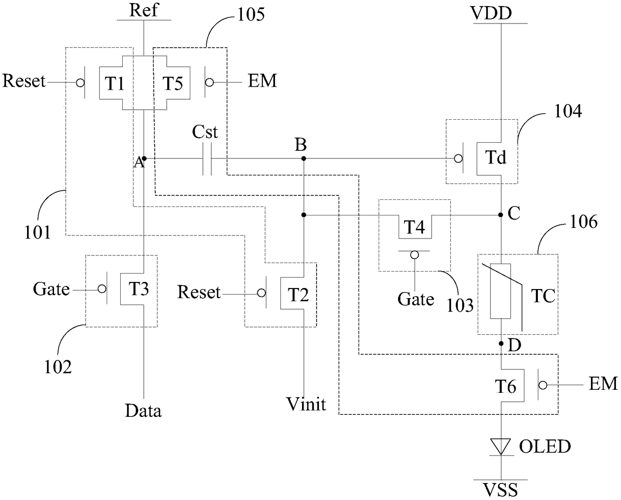
[0069] In the first embodiment, using figure 2 The pixel circuit shown drives the blue light-emitting device to emit light, while using Figure 4 The pixel circuit shown drives the red light emitting device and the green light emitting device to emit light.

[0070] It should be noted, figure 2 The pixel circuit shown with Figure 4 The working process of the pixel circuit shown is similar, the difference is due to figure 2 The pixel circuit shown is compared to Figure 4 The pixel circuit shown adds a thermistor TC such that figure 2 The pixel circuit shown can adjust the current flowing through the monochromatic light-emitting device according to the temperature change, thereby adjusting the brightness of the monochromatic light-emitting device. figure 2 The operation of the pixel circuit shown is described in detail. Figure 4 The working process of the pixel circuit shown can be referred to figure 2 The working process of the pixel circuit shown is not repeate...

Embodiment 2

[0086] In the second embodiment, using figure 2 The pixel circuit shown drives the red light emitting device Red OLED and the green light emitting device Green OLED to emit light, and figure 2 A positive temperature coefficient thermistor is set in the pixel circuit shown, and a positive temperature coefficient thermistor is also used Figure 4 The shown pixel circuit drives the blue light emitting device Blue OLED to emit light.

[0087] It should be noted that due to figure 2 The process of driving the red light emitting device Red OLED and the green light emitting device Green OLED to emit light by the pixel circuit shown is similar to the process of driving the blue light emitting device Blue OLED to emit light, so only the differences will be described below, and the repetition will not be repeated. Repeat.

[0088] Specifically, under the condition that the thermistor TC is a positive temperature coefficient thermistor PTC, and the monochromatic light-emitting devi...


PUM


Abstract

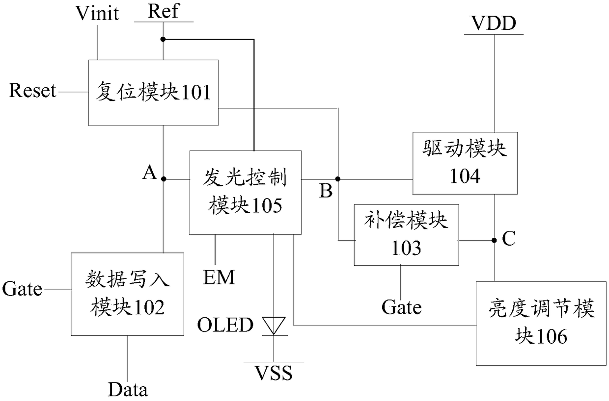
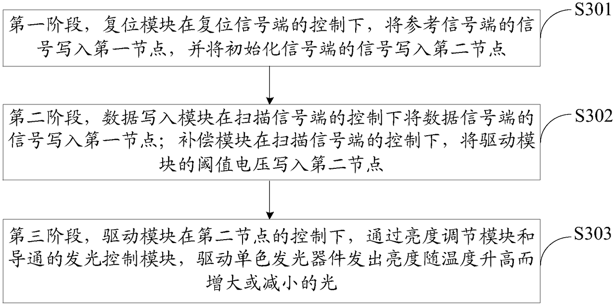
The invention discloses a pixel circuit, a driving method thereof, and a display panel. The pixel circuit comprises a resetting module, a data writing module, a compensation module, a driving module,a lighting control module, a brightness adjusting module and a monochrome light emitting device. Since the driving module drives a monochrome light emitting device to emit light whose brightness increases or decreases with increasing temperature through the brightness adjusting module and the turned-on light emitting control module, the brightness ratio changes of the red, green and blue three-color light emitting devices can be little or not change under high temperature conditions, thereby ensuring the stability of the white balance of the mixed white light of the red, green and blue three-color light-emitting devices under high temperature conditions.

Description

technical field [0001] The present invention relates to the field of display technology, and in particular, to a pixel circuit, a driving method thereof and a display panel. Background technique [0002] With the popularization of the Internet and the continuous development of display technology, high-quality display panels have become an important feature of many electronic consumer products. Compared with liquid crystal display panels, organic electroluminescent display panels have the advantages of self-luminescence, low energy consumption, low production cost, wide viewing angle, high contrast ratio, fast response speed, more vivid color display, easier realization of thinning and flexibility, etc. advantage. At present, in the display fields of mobile phones, digital cameras, computers, personal digital assistants, etc., organic electroluminescence display panels have begun to replace traditional liquid crystal display panels, and are expected to become the mainstream ...

Claims


Application Information

Patent Timeline
Patent Type & Authority Applications(China)
IPC IPC(8): G09G3/3225
CPCG09G3/3225
Inventor 晏荣建张俊瑞周全国王志东周丽佳兰荣华
Owner BOE TECH GRP CO LTD
Learn More