A kind of rotating laser light for dance hall

A laser and dance hall technology, applied in reflectors, lighting auxiliary devices, lighting and heating equipment, etc., can solve the problems of high energy consumption of dance hall lights, achieve better effects, improve practicability, and increase the effect of lighting atmosphere

Active Publication Date: 2021-02-19
王连富
View PDF7 Cites 0 Cited by
  • Summary
  • Abstract
  • Description
  • Claims
  • Application Information

AI Technical Summary

Problems solved by technology

On the one hand, the trajectory of the changing light is less fixed, and on the other hand, the positioning device drives the overall rotation of the ballroom lights to consume a lot of energy. Therefore, we propose a rotating laser light for ballrooms.

Method used


Image

  • A kind of rotating laser light for dance hall

Examples


Embodiment Construction

[0012] The following will clearly and completely describe the technical solutions in the embodiments of the present invention with reference to the accompanying drawings in the embodiments of the present invention. Obviously, the described embodiments are only some, not all, embodiments of the present invention. Based on the embodiments of the present invention, all other embodiments obtained by persons of ordinary skill in the art without making creative efforts belong to the protection scope of the present invention.

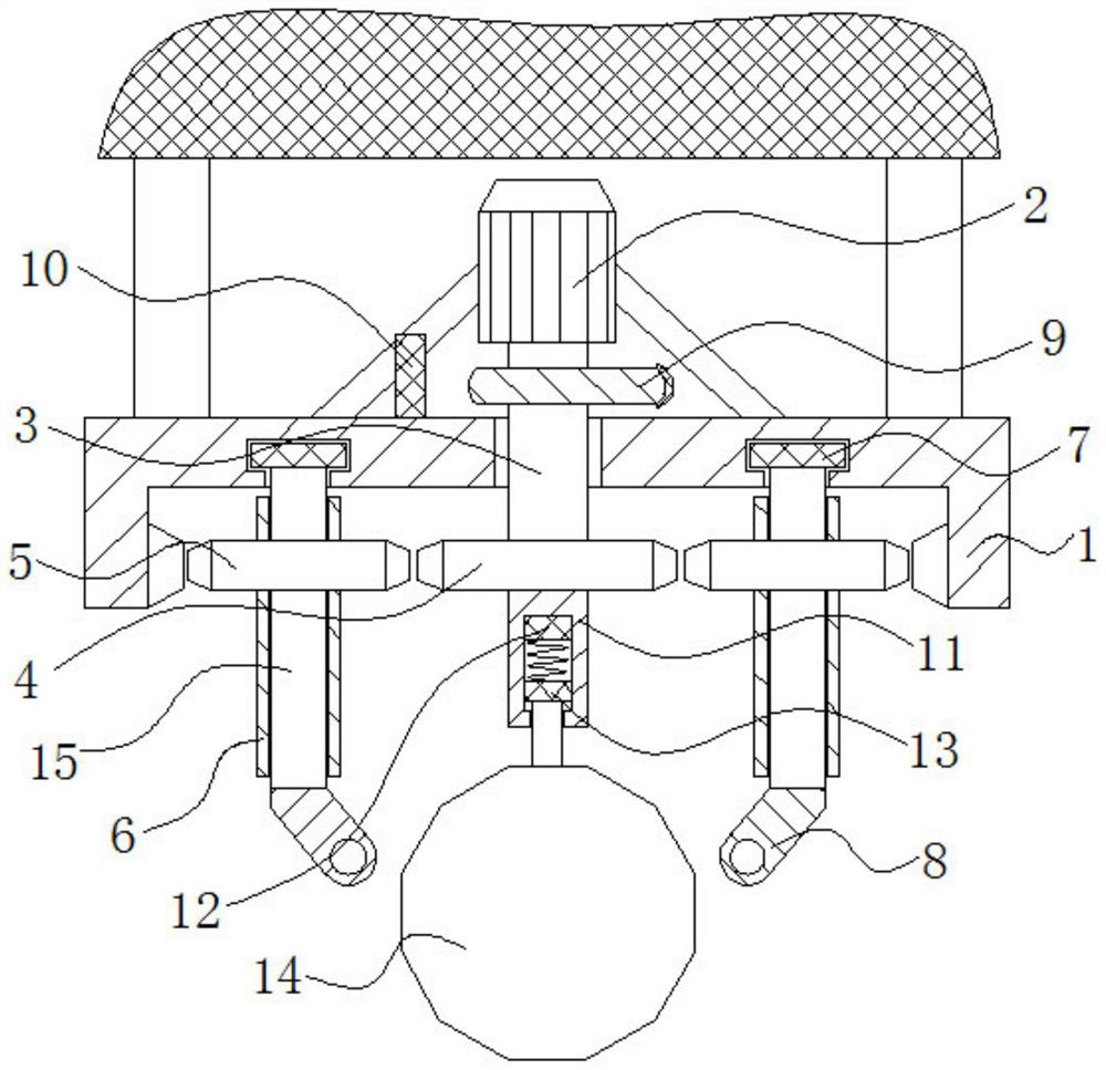
[0013] see figure 1 , the present invention provides a technical solution:

[0014] A rotating laser light for a dance hall, including a ring gear 1, the upper end of the ring gear 1 is symmetrically connected vertically with the lower ends of two support rods, and the upper ends of the two support rods are fixedly connected with the lower end of the ceiling, and the middle part of the upper end of the ring gear 1 passes through The bracket is fixedly connect...


PUM


Abstract

The invention discloses a rotary laser light for a ballroom. The rotary laser light for the ballroom comprises a gear ring. The rotary laser light for the ballroom is simple in structure. Three laserlight bodies project light to a specular reflection ball which reflects laser light to the ballroom. A motor is started to drive a sun wheel to rotate, and the specular reflection ball starts to rotate to reflect the laser light from multiple angles. Meanwhile, the sun wheel is engaged to three planet wheels to drive the planet wheels to rotate at velocities different from the sun wheel in frequency to drive the three laser light bodies to refract, so that the effect is better; meanwhile, a cam fixed connected to a first rotary shaft in a sleeving mode rotates, a copper layer of a bump part ofthe cam is in contact with a static contact piece intermittently, a circuit communicates, and an electromagnet is electrified to generate magnetism to adsorb an iron block intermittently to drive thespecular reflection ball to move up and down while rotating, so that the reflecting angles are more diversified, and therefore, the light atmosphere of the ballroom is increased and the practicalityis improved greatly.

Description

technical field [0001] The invention relates to the field of lamps, in particular to a rotating laser lamp for a dance hall. Background technique [0002] Ballroom lights are widely used in dance halls, KTV, performance scenes, etc., and the atmosphere can be created by changing the color and brightness of the ballroom lights. However, the color change and brightness change of the ballroom lamp usually rely on the rotation of the positioning device to change the refraction angle of the polygonal sphere with a fluorescent layer on the outside of the ballroom lamp to produce color changes, and the periodic changes of the power supply realize the brightness change. Dynamic atmosphere. Most of the existing dance hall lights are controlled by a positioning device to rotate as a whole, so that the light of the dance hall lights changes in a period of several seconds or tens of seconds. On the one hand, the trajectory of the changing light is less fixed, and on the other hand, th...

Claims


Application Information

Patent Timeline
Patent Type & Authority Patents(China)
IPC IPC(8): F21S8/00F21V21/096F21V7/00
CPCF21S8/00F21V7/00F21V21/096
Inventor 王连富
Owner 王连富
Why Eureka
Try Eureka