
Anti-floating dense construction method of hollow floor slab and thin-wall square box used in same

A hollow floor slab and construction method technology, applied in the direction of floor slabs, building components, buildings, etc., can solve the problems of easy occurrence of holes, waste of steel bars and labor, and poor lateral displacement control effect of square boxes, etc., to achieve enhanced strength and tightness. The effect of saving steel bars and workers' binding points, and improving the quality of the project

Inactive Publication Date: 2018-11-23
CHINA FIRST METALLURGICAL GROUP
View PDF10 Cites 10 Cited by
  • Summary
  • Abstract
  • Description
  • Claims
  • Application Information

AI Technical Summary

Problems solved by technology

[0002] In the construction of thin-walled square boxes with hollow floors, since the box itself is hollow, large buoyancy and side pressure will be generated during concrete pouring. The traditional method is to add long anti-floating ribs on the upper part of the box to fix the box. Not only is a lot of steel and labor wasted, but also the lateral displacement control effect of the other box is not good.
Moreover, due to the large area of ​​the square box, the traditional process cannot vibrate the bottom of the square box. It is difficult to completely flow the concrete into the bottom of the square box by vibrating around it. Holes are prone to appear after the formwork is removed, and the adhesion and strength of the bottom concrete cannot be guaranteed. Therefore, a new construction technology is urgently needed to solve these problems

Method used


Image

  • Anti-floating dense construction method of hollow floor slab and thin-wall square box used in same
  • Anti-floating dense construction method of hollow floor slab and thin-wall square box used in same
  • Anti-floating dense construction method of hollow floor slab and thin-wall square box used in same

Examples


Embodiment Construction

[0031] The present invention is illustrated below in conjunction with the accompanying drawings.

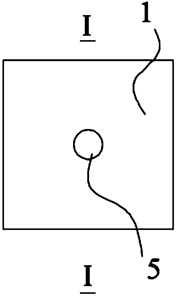
[0032] As shown in the figure, a thin-walled square box for anti-floating and dense construction of hollow floor slabs, the thin-walled square box 1 has a regular polygonal cross section and an isosceles trapezoidal longitudinal section, which together form a closed box structure with a large upper part and a smaller lower part. The middle part of the box structure is provided with a through-hole 5 that runs through the upper and lower sides, and the through-hole 5 is sealed and isolated from the inner space of the airtight box; Reinforcing groove 9.

[0033] More preferably, the bottom of the thin-walled square box 1 is provided with anti-floating tension ribs, and the anti-floating tension ribs are provided with installation holes for pulling knots. The transverse section of the thin-walled square box 1 is a regular quadrilateral or regular octagon. This embodiment uses The op...


PUM


Abstract

The invention discloses an anti-floating dense construction method of a hollow floor slab and a thin-wall square box used in the same, wherein the middle part of the thin-wall square box is provided with a through hole which run through the upper part and the lower part, and the through hole is sealed and isolated from the inner space of the closed box body; during construction, a bottom rib is pulled and installed on the support member below the framework, then the thin-wall square box is placed, and the bottom of the thin-wall square box and the bottom rib are pulled and combined; a plurality of pulling wires shaped like a Chinese character 'Ji' are arranged between the connecting line of the central axes of adjacent thin-wall square boxes, the middle submerging part of the pulling wireshaped like the Chinese character 'Ji' are pulled and fastened on the bottom rib, and a surface rib is bonded, the concrete are poured for two times, a vibrating rod is used for vibrating and compacting through the gap between adjacent thin-wall square boxes and through hole in the middle of the thin-wall square box every time of casting. According to the invention, the anti-floating effect of thethin-wall square box is ensured, the lateral sliding of the thin-wall square box can be effectively prevented, the concrete at the bottom of the box body is more compact, and the quality of the floorstructure can be ensured while the steel and the installation time are greatly saved.

Description

technical field [0001] The invention belongs to the field of pouring construction, and relates to a hollow floor construction technology, in particular to a construction method for anti-floating and dense construction of a hollow floor slab and a thin-walled square box used in the method. Background technique [0002] In the construction of thin-walled square boxes with hollow floors, since the box itself is hollow, large buoyancy and side pressure will be generated during concrete pouring. The traditional method is to add long anti-floating ribs on the upper part of the box to fix the box. Not only wasting a lot of steel bars and labor, but also the lateral displacement control effect of the other box is not good. Moreover, due to the large area of ​​the square box, the traditional process cannot vibrate the bottom of the square box. It is difficult to completely flow the concrete into the bottom of the square box by vibrating around it. Holes are prone to appear after the ...

Claims


Application Information

Patent Timeline
IPC IPC(8): E04B5/32
Inventor 宋鹏田红云郭继舟
Owner CHINA FIRST METALLURGICAL GROUP
Learn More