Eureka AIR delivers breakthrough ideas for toughest innovation challenges, trusted by R&D personnel around the world.

Sealed quantitative feeding machine and control system thereof

A vibrating feeder and control system technology, applied in conveyors, conveyor objects, transportation and packaging, etc., can solve the problems of large volume, poor air-locking effect, and high failure rate, and achieve small size, convenient operation, and improved performance. The effect of sealing performance

Pending Publication Date: 2018-11-23
ANHUI WEIQIONG DRIVING TECH CO LTD
View PDF0 Cites 9 Cited by
  • Summary
  • Abstract
  • Description
  • Claims
  • Application Information

AI Technical Summary

Problems solved by technology

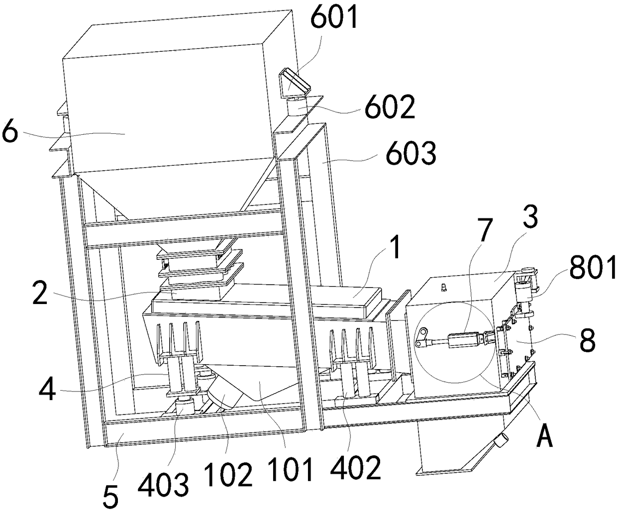
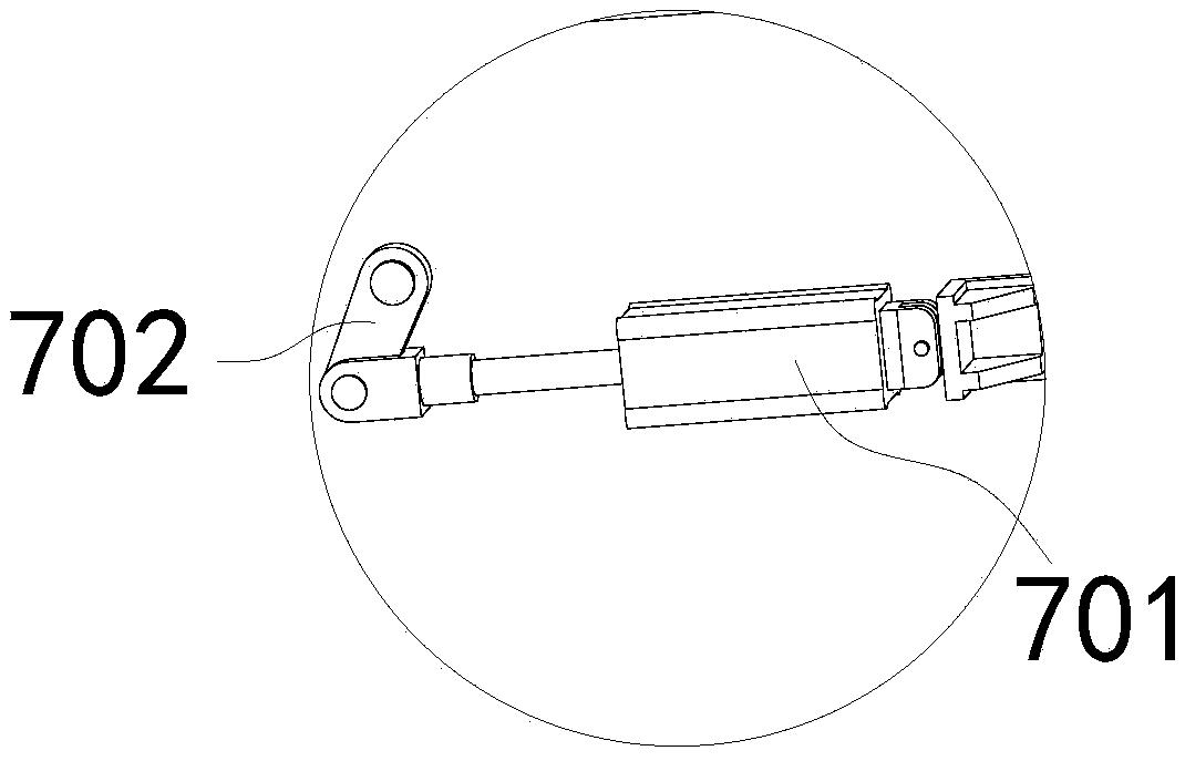
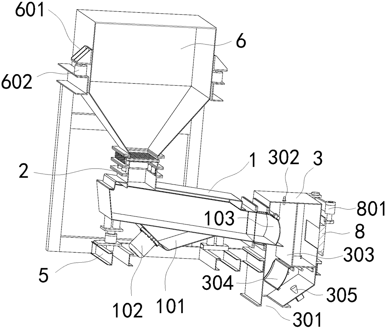
[0005] The purpose of the present invention is to provide a closed quantitative vibrating feeder and its control system. The material first passes through the weighing bin and then enters the vibrating bin through the feeding channel for vibrating feeding, and then passes through the weighing bin in the metering bin. The pressure sensor calculates the material flow and the anti-rotation material level sensor judges the blocking situation, and through the material level control of the weighing silo, the flow control of the material and the feedback of the pressure difference sensor, the material is effectively used in the weighing silo discharge channel and The material in the vibrating feeder is accumulated to ensure its air lock effect, which solves the problems of poor air lock effect, high failure rate and large volume of the existing feeder

Method used


Image

  • Sealed quantitative feeding machine and control system thereof
  • Sealed quantitative feeding machine and control system thereof
  • Sealed quantitative feeding machine and control system thereof

Examples


Embodiment Construction

[0043]The following will clearly and completely describe the technical solutions in the embodiments of the present invention with reference to the accompanying drawings in the embodiments of the present invention. Obviously, the described embodiments are only some, not all, embodiments of the present invention. Based on the embodiments of the present invention, all other embodiments obtained by persons of ordinary skill in the art without creative efforts fall within the protection scope of the present invention.

[0044] In the description of the present invention, it should be understood that the terms "arrangement", "bottom surface", "top surface", "bottom", "length", "inner", "side outer wall", etc. indicate orientation or positional relationship, and are only In order to facilitate the description of the present invention and simplify the description, it does not indicate or imply that the components or elements referred to must have a specific orientation, be constructed ...


PUM


Abstract

The invention discloses a sealed quantitative feeding machine and a control system thereof, and relates to the technical field of vibrating feeding. The machine comprises a vibrating delivering chamber, and the two ends of the vibrating delivering chamber are fixedly communicated with a discharging passage and a measuring chamber through glued canvases; the bottom side face of the vibrating delivering chamber is connected with a fixing frame through two groups of elastic buffering mechanisms, a vibrating motor supporting frame is fixed to the bottom face of the vibrating delivering chamber, and a plurality of vibrating motors are fixed to the vibrating motor supporting frame; a weighing chamber is fixedly communicated with the top of the discharging passage. According to the machine, materials pass through the weighing chamber and the discharging passage and enter the vibrating delivering chamber to be vibrated and discharged, material flow rate is calculated by pulling a pressure sensor in the measuring chamber, and the blockage situation is judged by a damped rotation material level sensor in the measuring chamber; air locking effect of the feeding machine is improved by maintaining the material level of the weighing chamber and flow rate control, the structure is simple, the faulting rate is low, and the size of the feeding machine is effectively reduced.

Description

technical field [0001] The invention belongs to the technical field of metering feeders, in particular to an airtight quantitative vibrating feeder and its control system. Background technique [0002] Vibrating feeder, also known as vibrating feeder, refers to a kind of equipment that can uniformly, quantitatively and continuously feed block, granule, powder or the mixture of these three forms to the receiving device. As the vertical mill is widely used in many industries, the vertical mill system is operated under negative pressure and high temperature, so the corresponding feeding mechanism is required to have an airtight air lock device; while the vertical mill has a large feeding volume, the material is uneven in size and material, and It is mixed with powdery materials, and in some areas, there are also characteristics of high humidity and high viscosity of materials. [0003] The initial vertical mill feeding devices, such as rotary valves and three-way air lock valv...

Claims


Application Information

Patent Timeline
Patent Type & Authority Applications(China)
IPC IPC(8): B65G47/19
CPCB65G47/19B65G2201/042
Inventor 丁雷王刚刘伟
Owner ANHUI WEIQIONG DRIVING TECH CO LTD
Why Eureka
Eureka Blog
Learn More