
Pharmaceutical heat-preserving dispensing tank

A liquid dispensing tank and inner tank technology, which is applied in the field of pharmaceutical thermal insulation liquid dispensing tanks, can solve the problems of difficulty in ensuring the temperature uniformity of the internal medicinal liquid, affecting the quality of medicinal liquid preparation, and uneven internal temperature, so as to achieve rapid pharmaceutical production and reduce Quality, the effect of realizing energy-saving production

Inactive Publication Date: 2018-11-23
WUHU KANGQI PHARMA
View PDF11 Cites 2 Cited by
  • Summary
  • Abstract
  • Description
  • Claims
  • Application Information

AI Technical Summary

Problems solved by technology

At present, most of the stirring mechanisms in the liquid mixing tank commonly used now use one-way stirring, and the stirring efficiency is not high. It is difficult to ensure the uniformity of the temperature of the internal liquid medicine, which is not conducive to the preparation of the liquid medicine to a certain extent, and affects the quality of the liquid medicine preparation
[0003] The utility model with the patent number CN201720083716.1 discloses a coil-type liquid distribution tank, which includes an inner tank, the inner tank is in the shape of a cylinder, the top of the inner tank is provided with an upper head of the inner tank, and the inner tank is The bottom end of the tank is provided with a lower head of the liner, and several legs are arranged under the lower head, and the lower heads are evenly arranged under the lower head, and the lower head stands on the ground through the legs. A stirring shaft is longitudinally arranged in the inner tank, and several layers of stirring blades are arranged on the longitudinal direction of the stirring shaft, and each layer of stirring blades includes several stirring blades detachably connected with the stirring shaft. A coiled tube is coiled around the outer surface of the lower head of the liner, and the outer surface of the inner liner and the lower head of the inner liner are both laid with an insulating layer, and the insulating layer covers the outside of the coiled tube, and the bottom of the coiled tube is set There is a cooling water / hot water inlet, and the top of the coil is provided with a hot water / cooling water outlet. The liquid distribution tank still adopts the traditional one-way stirring structure, which still has the disadvantage of low stirring efficiency. At the same time, the coil The structure is used for heat preservation, and a whole-area heat preservation structure is not used outside the tank, and there is also the possibility of uneven internal temperature during the dispensing process

Method used


Image

  • Pharmaceutical heat-preserving dispensing tank
  • Pharmaceutical heat-preserving dispensing tank
  • Pharmaceutical heat-preserving dispensing tank

Examples


Embodiment 1

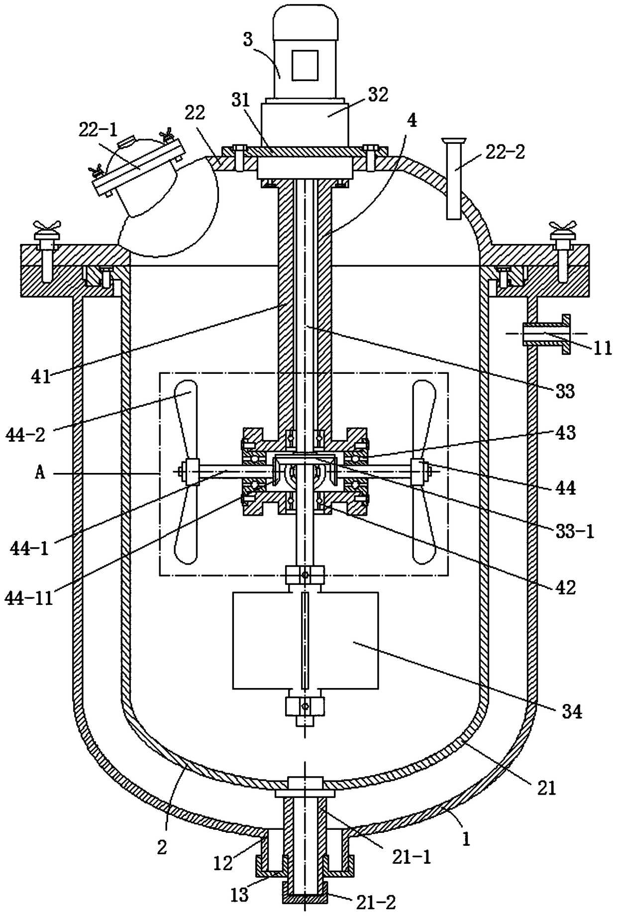
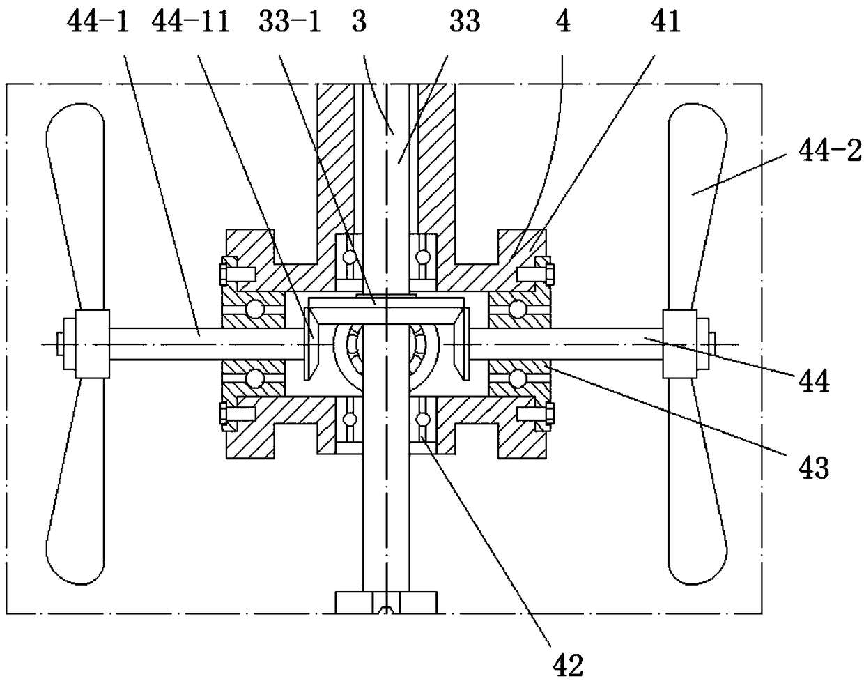
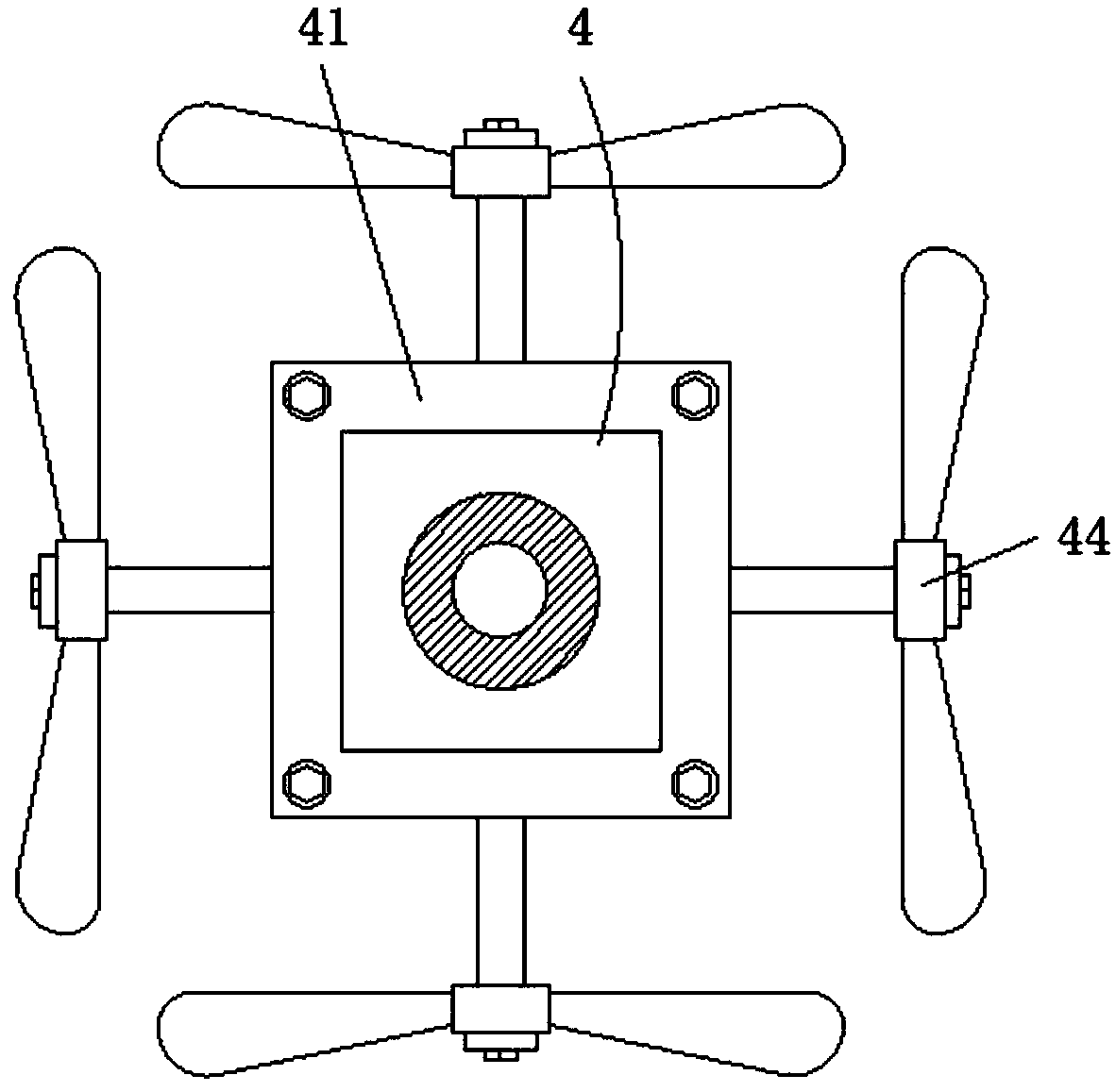
[0025] A heat-preserving liquid mixing tank for pharmaceuticals with a structure of the present invention has high liquid mixing and stirring efficiency. Specifically, the medicinal liquid to be mixed is poured from the manhole 22-1, and then the reduction motor 32 is started, and the reduction motor 32 will Drive the rotating shaft 33 to rotate. On the one hand, the cross stirring blade 34 fixedly installed on the rotating shaft 33 will rotate with the rotation of the rotating shaft 33, so that the cross stirring blade 34 will stir the medicinal liquid in the horizontal direction. On the other hand, the driving The bevel gear 33-1 will drive the driven bevel gear 44-11 meshed with it, thereby driving the driven bevel gear 44-11 to rotate, that is, driving the driven shaft 44-1 to rotate along the horizontal bearing 43, and then the paddle 44 -2 With the rotation of the driven shaft 44-1, the paddles 44-2 of the four driven stirring components 44 will stir the liquid medicine i...

Embodiment 2

[0027]A thermal insulation liquid mixing tank for pharmaceuticals with the structure of the present invention has a good thermal insulation effect. Specifically, an effective thermal insulation material layer is sprayed on the inner layer of the outer tank body 1, which reduces the temperature transfer between the outer tank body 1 and the surrounding environment In addition, the inner tank body 21 is clipped and fixedly installed on the upper end of the outer tank body 1, forming a gap layer between the inner tank body 21 and the outer tank body 1, avoiding direct contact between the inner tank body 21 and the surrounding environment. Contact, that is, to avoid direct temperature exchange, at the same time, the water at the temperature required for dispensing can be introduced through the water inlet flange pipe 11 on the outer tank body 1, and the gap between the outer tank body 1 and the inner tank body 21 can be filled. The gap forms an effective water insulation layer. The...


PUM


Abstract

The invention discloses a pharmaceutical heat-preserving dispensing tank, and relates to the technical field of pharmaceutical equipment. The pharmaceutical heat-preserving dispensing tank comprises an outer tank body, inner tank components, a driving stirring mechanism and a driven stirring mechanism, wherein the inner tank components comprise a inner tank body and a inner tank cover; the drivingstirring mechanism comprise a fixing plate, a gear motor, a rotating shaft and crossed agitation blades; the driven stirring mechanism comprise an hanger bearing frame, a vertical bearing, an lateralbearing and driven stirring components; the pharmaceutical heat-preserving dispensing tank adopts the stirring method of multi-directional stirring for higher stirring efficiency and providing an environment with more even and stable temperature during drug solution preparation.

Description

technical field [0001] The invention relates to the technical field of pharmaceutical equipment, in particular to a thermal insulation liquid dispensing tank for pharmaceuticals. Background technique [0002] The liquid mixing tank, also known as the preparation tank and the blending tank, is a mixing and stirring container that mixes one or several materials according to the process ratio. The manufactured liquid mixing tank is a modern GMP that is manufactured and accepted according to the pharmaceutical sanitary standards of the pharmaceutical industry. standard equipment. At present, most of the stirring mechanisms in the liquid mixing tank commonly used now use one-way stirring, and the stirring efficiency is not high. It is difficult to ensure the uniformity of the temperature of the internal liquid medicine, which is not conducive to the preparation of the liquid medicine to a certain extent, and affects the quality of the liquid medicine preparation. [0003] The u...

Claims


Application Information

Patent Timeline
Patent Type & Authority Applications(China)
IPC IPC(8): B01F7/30B01F15/00
CPCB01F27/951B01F35/2215B01F2101/22
Inventor 张勇徐海东端木于良阮西亮
Owner WUHU KANGQI PHARMA
Learn More