
Environment-friendly gas absorption device used in chemical workshop, and using method of environment-friendly gas absorption device

A suction device and workshop technology, applied to chemical instruments and methods, separation methods, and separation of dispersed particles, can solve the problems of inconvenient and timely adjustment of air output, inability to absorb fine particles, and inability to adjust installation height, etc., to ensure installation Convenience, ensure the accuracy of inhalation, and ensure the effect of adsorption efficiency

Active Publication Date: 2018-11-23
江苏爱科固体废物处理有限公司
View PDF12 Cites 3 Cited by
  • Summary
  • Abstract
  • Description
  • Claims
  • Application Information

AI Technical Summary

Problems solved by technology

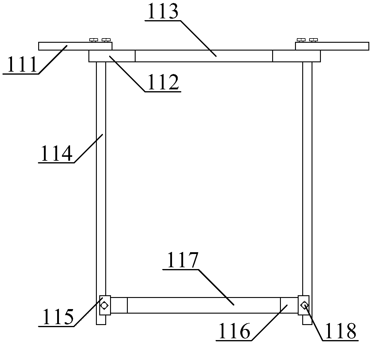
[0006] In order to solve the above-mentioned technical problems, the present invention provides an environmental-friendly suction device and its usage method for chemical workshops, to solve the problem that the existing environmental-friendly suction devices and usage methods of chemical workshops cannot adjust the installation height, and the discharged gas is easy to be mishandled. Pollution of the environment, unable to sample and detect the gas in the workshop, unable to adsorb fine particles before exhausting the gas, and inconvenient to adjust the gas output in time. An environmentally friendly suction device for chemical workshops, including rubber caps, chemical reagent boxes, suction pumps, Catheter, suction cover, spraying row, spraying head, air impurity adsorption wheel structure, gas sample absorption back sample bottle structure, gas impurity filtration suction guide fan, adjustable quick installation frame, gas guide metal hose, The connecting seat, the support frame and the adjustable cover structure of the exhaust volume, the rubber cap is threadedly connected to the upper right inlet of the chemical agent box; the suction pump bolt is installed in the middle position of the upper left side of the chemical agent box; One end of the above-mentioned catheter tube runs through the upper right side of the suction hood and is threaded to the upper right inlet of the spraying row, and the other end is threaded to the left outlet of the suction pump; the screw of the spraying row is connected to the suction hood The middle position of the inner right wall of the inner side; the spray head is threaded on the left side of the spray row from top to bottom; the air impurity adsorption wheel structure is installed in the middle position of the lower part of the suction hood; the gas The structure of the sample absorption and return sample bottle is installed in the middle position on the upper left side of the suction hood; as mentioned, one end of the gas impurity filtering suction guide fan is connected to the upper end of the suction hood, and the other end is connected to the inner lower part of the adjustable quick installation frame; The air-conducting metal hose runs through the inner middle position of the adjustable quick installation frame and the lower end is connected with the air impurity filter suction fan; the connecting seats are installed horizontally on the left and right sides of the upper part of the adjustable quick installation frame; One end of the supporting frame is connected to the adjustable cover structure of exhaust volume, and the other end is bolted to the connecting seat; the adjustable quick mounting frame includes a mounting seat, a connecting seat, a through hole, a linear slide rail, a U-shaped slider, and a movable seat , circular holes and locking bolts, the mounting seats are installed on the left and right sides of the upper part of the connecting seat with the horizontal inner section bolts respectively; the through holes are opened in the inner middle position of the connecting seat; The longitudinal upper end bolts are installed on the left and right sides of the lower part of the connecting seat; the U-shaped sliders are respectively slid and clamped on the inner lower part of the linear slide rail; the horizontal bolts of the movable seat are installed in the middle position between the U-shaped sliders; The circular hole is opened in the middle of the inner side of the movable seat; the locking bolts are respectively threaded at the junction of the U-shaped slider and the linear slide rail

Method used

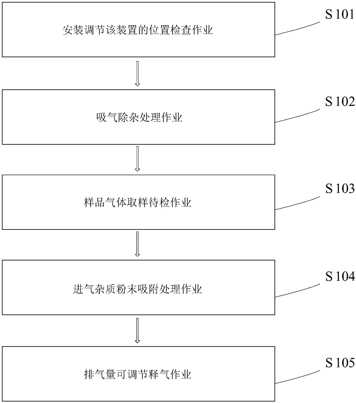

Image

  • Environment-friendly gas absorption device used in chemical workshop, and using method of environment-friendly gas absorption device
  • Environment-friendly gas absorption device used in chemical workshop, and using method of environment-friendly gas absorption device
  • Environment-friendly gas absorption device used in chemical workshop, and using method of environment-friendly gas absorption device

Examples


Embodiment Construction

[0057] The present invention will be further described below in conjunction with accompanying drawing:

[0058] In the picture:

[0059] as attached figure 2 to attach Figure 7 shown

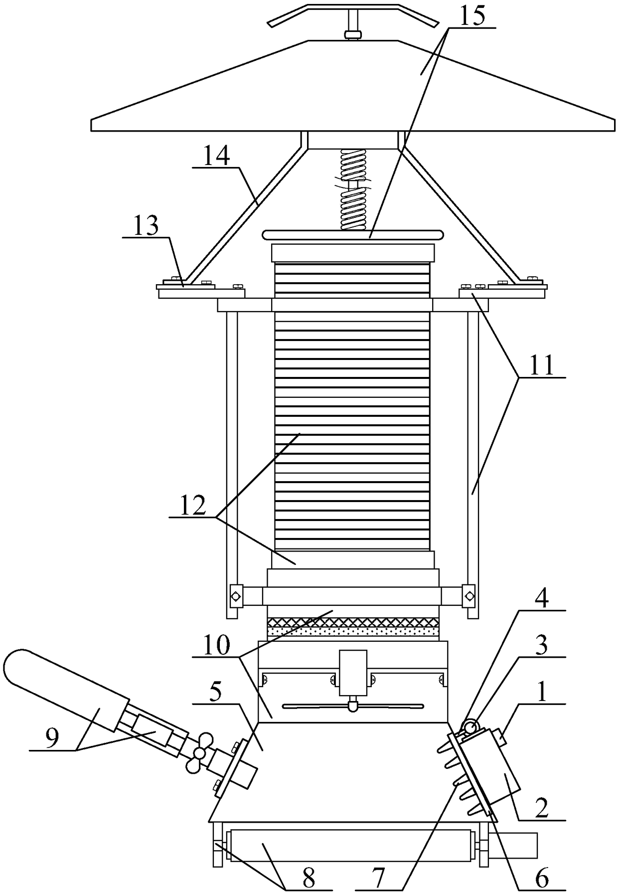
[0060] An environment-friendly suction device for a chemical workshop, including a rubber cap 1, a chemical agent box 2, a suction pump 3, a catheter 4, a suction cover 5, a spraying row 6, a spraying head 7, and an air impurity adsorption wheel structure 8, Gas sample absorbing sample bottle structure 9, gas impurity filtering suction fan 10, adjustable quick mounting frame 11, gas guiding metal hose 12, connecting seat 13, support frame 14 and adjustable displacement cover structure 15, The rubber cap 1 is threadedly connected to the entrance of the upper right part of the chemical agent box 2; the bolt of the suction pump 3 is installed in the middle position of the upper left side of the chemical agent box 2; one end of the catheter 4 runs through the suction hood The upper right side ...


PUM


Abstract

The invention provides an environment-friendly gas absorption device used in a chemical workshop. The device comprises a rubber cap, a chemical agent tank, a suction pump, a liquid guiding tube, a gasabsorption hood, a chemical agent spray strip, spray nozzles, an air impurity absorption wheel structure, a gas sample absorption and return bottle structure, a gas impurity filter gas-suction guidefan, an adjustable quick mounting rack, a gas guide metal hose, a connecting seat, a support frame and an exhaust volume adjustable baffle cover structure, wherein the rubber cap is connected with anentrance at the right upper part of the chemical agent tank by means of screw threads. The environment-friendly gas absorption device solves the problems that the installation height cannot be adjusted, environmental pollution is easily caused by the improperly treated gas, the gas in the workshop cannot be sampled and detected, the fine particles cannot be absorbed before the gas is exhausted, and the gas output is not conveniently adjusted timely.

Description

technical field [0001] The invention belongs to the technical field of environmental protection equipment for chemical workshops, and in particular relates to an environmental protection suction device for chemical workshops and a method for using the same. Background technique [0002] In the production process of each enterprise, in order to achieve a suitable environment such as hygiene and safety, it is necessary to ventilate the production environment, so ventilation equipment is required; most of the ventilation equipment used by existing enterprises is installed on the wall When the exhaust fan is working, the position of the exhaust fan cannot be adjusted according to the needs of production, and it cannot meet different production needs. [0003] At present, China's published patent No. is CN205066030U, and the name of the invention is a kind of environmental protection ventilation equipment for chemical workshops, including: fixed beams, sliding beams, mounting sea...

Claims


Application Information

Patent Timeline
IPC IPC(8): B01D46/00B01D46/10B01D53/78
CPCB01D46/0036B01D46/0038B01D46/10B01D53/78
Inventor 刘玉洁
Owner 江苏爱科固体废物处理有限公司
Learn More