
Vehicle-mounted cardiopulmonary resuscitation robot

A cardiopulmonary resuscitation and robot technology, applied in cardiac stimulation, artificial respiration, physical therapy, etc., can solve problems such as inconvenient feeling, fatigue of rescuers, lack of space, etc., and achieve light weight, simple structure, and stable chest compression The effect of speed and force

Active Publication Date: 2018-11-23
江苏康康同学科技有限公司
View PDF6 Cites 2 Cited by
  • Summary
  • Abstract
  • Description
  • Claims
  • Application Information

AI Technical Summary

Problems solved by technology

The current emergency work is usually carried out manually, especially in the ambulance, which requires continuous cardiopulmonary resuscitation, because manual operation is very easy to cause fatigue to the rescuers, so the rescuers are usually alternated, but this is unavoidable pause
In addition, to perform chest compressions, the rescuer needs to stand upright to use force. Because the space on the ambulance is small, it will be more inconvenient to perform chest compressions.
Space on an ambulance is at a premium and adding a common CPR unit will make the existing space even more scarce

Method used


Image

  • Vehicle-mounted cardiopulmonary resuscitation robot
  • Vehicle-mounted cardiopulmonary resuscitation robot
  • Vehicle-mounted cardiopulmonary resuscitation robot

Examples


Embodiment 1

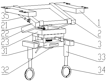
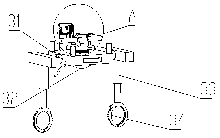
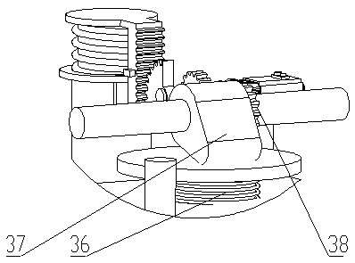
[0024] see Figure 1 to Figure 4 , the present invention provides a vehicle-mounted cardiopulmonary resuscitation robot, including a top frame 1 fixedly connected to the inside of the roof of the ambulance, the top frame 1 is connected to a chest compression mechanism 3 through a folding frame 2, and the chest compression mechanism 3 includes a base plate 31, a base plate 31 The middle part is provided with a pressing column 32, the pressing column 32 is vertically arranged, the bottom of the pressing column 32 is a spherical surface, and the upper part of the pressing column 32 is linked with the driving mechanism; both sides of the base plate 31 are symmetrically vertically provided with a fixed rod 33, and the fixed rod 33 A fixing clip 34 is arranged at the bottom, and the fixing clip 34 is a ring clip corresponding to the stretcher bar.

[0025] Folding frame 2 is " Z " font, comprises upper frame 21, middle frame 22 and lower frame 23, and the two ends of middle frame 21...

Embodiment 2

[0035]On the basis of Embodiment 1, the difference from Embodiment 1 is that the upper ends of the fixed rods 33 on both sides are rotatably connected with the two sides of the base plate 31, and a torsion spring is also set at the rotation position, so that the fixed rods 33 can be bent to be in line with the vehicle when stored. top parallel.


PUM


Abstract

The invention discloses a vehicle-mounted cardiopulmonary resuscitation robot and relates to the field of emergency equipment. The technological scheme includes a top frame fixedly connected with theinternal roof of an ambulance. The top frame is connected with a chest compression mechanism through a folding frame. The chest compression mechanism includes a base plate. A pressing column is arranged through the middle of the base plate. The pressing column is arranged vertically. The bottom of the pressing column is a spherical surface. The top of the pressing column is in linkage with a driving mechanism. A fixed rod is arranged symmetrically and vertically downward on two sides of the base plate. The bottom of the fixed rod is provided with a fixed clamp. The vehicle-mounted cardiopulmonary resuscitation robot has the advantages of being simple in structure and light in overall weight, not occupying space for other equipment and facilities, using a self-locking structure of handcuffsas a connecting part, which can save the connecting time of the vehicle-mounted cardiopulmonary resuscitation robot and a stretcher bed to the maximum extent, and using a push rod to switch for chestcompression and breathing mask ventilation through the combination of the chest compression mechanism and an air delivery cylinder, thereby simulating the operation process of alternating chest compression and artificial respiration in the process of the cardiopulmonary resuscitation.

Description

technical field [0001] The invention relates to the field of emergency equipment, in particular to a vehicle-mounted cardiopulmonary resuscitation robot. Background technique [0002] Cardiopulmonary resuscitation is an important means in the first aid process, which mainly includes two actions of chest compressions and artificial respiration, usually every 30 chest compressions combined with two artificial respirations, and each chest compression requires at least 5CM Compression stroke, compression frequency not less than 100 times per minute. The current emergency work is usually carried out manually, especially in the ambulance, which requires continuous cardiopulmonary resuscitation, because manual operation is very easy to cause fatigue to the rescuers, so the rescuers are usually alternated, but this is unavoidable There is a pause. In addition, to perform chest compressions, the rescuer needs to stand upright to use force. Because the space on the ambulance is smal...

Claims


Application Information

Patent Timeline
Patent Type & Authority Applications(China)
IPC IPC(8): A61H31/00
CPCA61H31/006A61H2201/1418A61H2201/1207
Inventor 梁聪聪
Owner 江苏康康同学科技有限公司
Learn More