Spine correction exercise device
An exercise device and spine technology, which is applied in the field of spine, can solve the problems of inability to control the spine correction independently, cannot grasp the amount of traction well, etc., and achieve the effect of enhanced practicability, ingenious structure, and strong practicability
- Summary
- Abstract
- Description
- Claims
- Application Information
AI Technical Summary
Problems solved by technology
Method used
Image

Examples
Embodiment 1
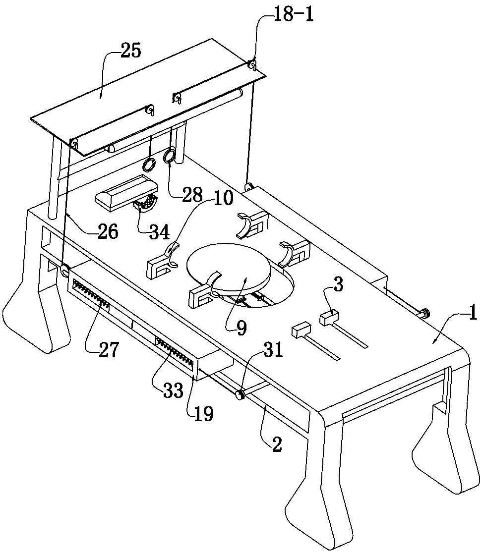
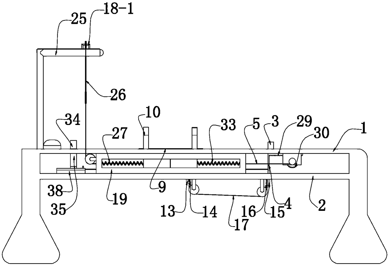
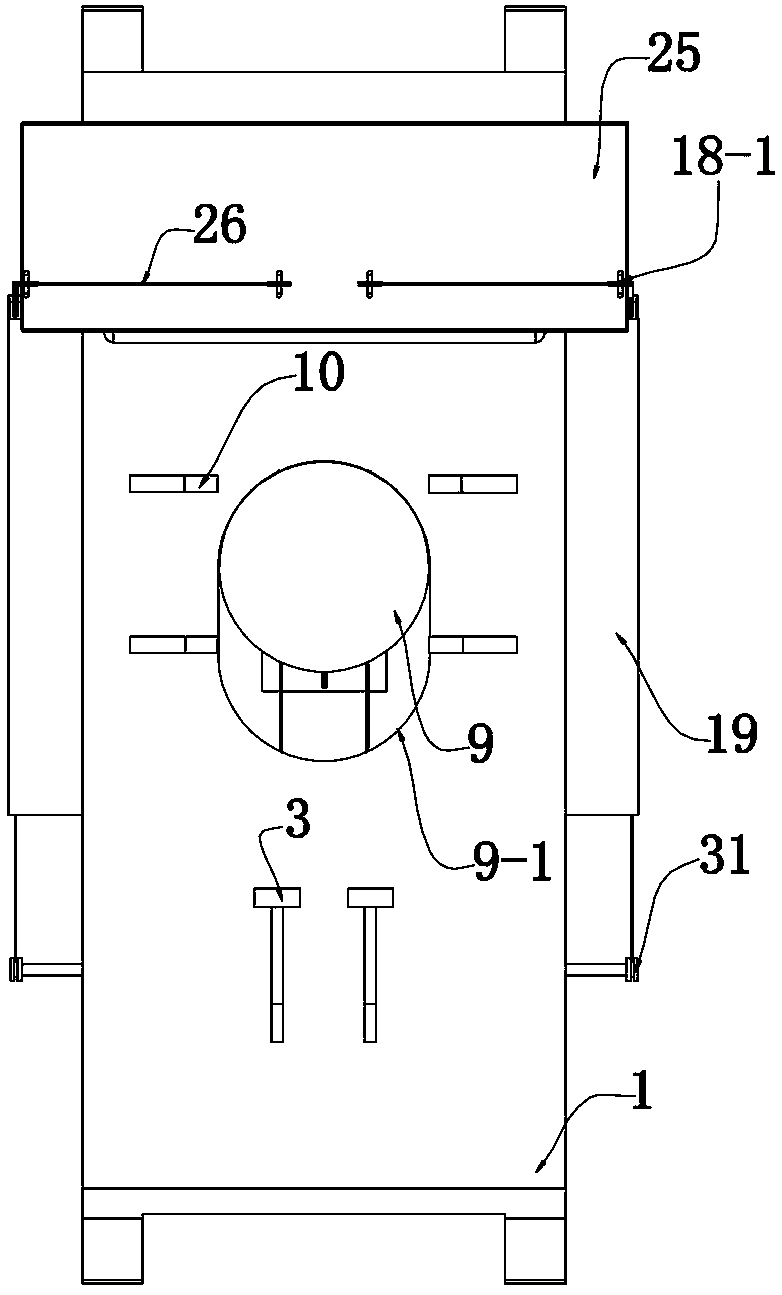
[0041] The first embodiment, the present invention is a spine correction exercise device, please refer to Image 6 , Including bed board 1 and storage board 2 placed at the lower end of bed board 1, spine correction users lie on the upper end of bed board 1 for exercise correction, please refer to figure 1 , The bed board 1 is provided with two leg kicks 3 in a sliding fit along the length direction. When the legs of the spine correction user are in the bent knee state in the initial state, the feet can press the two leg kicks 3 respectively, please refer to Figure 5 , The lower end of the leg step 3 is fixedly provided with a connecting plate 4, please refer to Figure 8 , The front ends of the two connecting plates 4 are fixed by connecting rods 5 with racks 6 which are slidably fitted with the storage plate 2 along the length direction. The connecting rods 5 play the role of connecting, and steel ropes, wire ropes, etc. can be used instead , The connecting rod 5 is placed at t...
Embodiment 2
[0048] In the second embodiment, on the basis of the first embodiment, in order to realize the movement of the correction top blocks 10 on both sides of the back toward the user, the user can control it by himself, so that the user can control the spine by himself, and better grasp the amount of traction. See figure 1 with Figure 5 , The upper end of the storage plate 2 is fixed with two hollow boxes 19 placed on both sides of the correction disc 9, please refer to Figure 14 with Figure 15 , The lower end of the correction top block 10 placed on both sides of the user's back is fixed with an L-shaped sliding rod 20 that penetrates the bed board 1, and the sliding rod 20 is slidingly fitted with the box 19 along the width direction of the bed board 1. 19 There is a channel 21 through which is provided with a sliding fit with the sliding rod 20, please refer to Picture 11 with Picture 12 The inside of the box 19 is provided with a wedge block 22 in a sliding fit along the leng...
Embodiment 3
[0053] In the third embodiment, on the basis of the second embodiment, in order to realize the movement of the correction top blocks 10 on both sides of the waist toward the user, the user can control it by himself, so that the user can control the spine by himself and better grasp the amount of traction. See Figure 5 The lower end of the correction top block 10 placed on both sides of the user’s waist is fixed with an L-shaped sliding rod 20 that penetrates the bed board 1, and the sliding rod 20 and the box 19 are slidingly fitted along the width direction of the bed board 1. 19 penetrates through a channel 21 that is slidingly fitted with the sliding rod 20. A wedge block 22 is slidably fitted inside the box 19 along the length of the bed board 1. The wedge block 22 is provided with a T-shaped groove facing the side of the correction disc 9 23. The sliding rod 20 is fixed with a T-shaped block 24 corresponding to the shape of the T-shaped groove 23, and the T-shaped block 24...
PUM
 Abstract
Description
Claims
Application Information
 - R&D
- Intellectual Property
- Life Sciences
- Materials
- Tech Scout
- Unparalleled Data Quality
- Higher Quality Content
- 60% Fewer Hallucinations
Browse by: Latest US Patents, China's latest patents, Technical Efficacy Thesaurus, Application Domain, Technology Topic, Popular Technical Reports.
© 2025 PatSnap. All rights reserved.Legal|Privacy policy|Modern Slavery Act Transparency Statement|Sitemap|About US| Contact US: help@patsnap.com