Obstetric-gynecology movable support

A mobile bracket, obstetrics and gynecology technology, applied in the field of brackets, can solve problems such as inability to support, scattered shaking, occupying space, etc., to achieve the effect of reducing occupied space and enhancing stability

Active Publication Date: 2018-11-20
山东瑞通高分子医疗器械有限公司
View PDF7 Cites 1 Cited by
  • Summary
  • Abstract
  • Description
  • Claims
  • Application Information

AI Technical Summary

Problems solved by technology

[0007] The purpose of the present invention is to solve the problem that the examination table support in the prior art is relatively large in size and takes up a lot of space. When it needs to be moved to a different location for use, it is prone to loose shaking and cannot be well stabilized. It is inconvenient to move; it cannot be supported according to the position of the legs and the angle to be opened during the examination, which leads to the disadvantage that the patient is prone to sore legs during the examination, and a mobile support for obstetrics and gynecology is proposed

Method used


Image

  • Obstetric-gynecology movable support
  • Obstetric-gynecology movable support
  • Obstetric-gynecology movable support

Examples


Embodiment 1

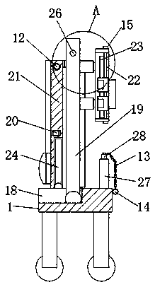
[0034] refer to figure 1 , 3and 6, a mobile bracket for obstetrics and gynecology, including a fixed base 1, one side of the fixed base 1 is provided with an accommodation groove 18, and both ends of the interior of the accommodation groove 18 are provided with first rotating shafts, and the two first rotating shafts The other side is rotatably connected with a first support frame 19, and a first fixing plate 7 is connected between the two first support frames 19. When the examination bed support is used in different places, the two first rotating shafts can be used to drive the two. The first support frame 19 and the first fixed plate 7 between the two first support frames 19 rotate, so that the first support frame 19 drives the two first fixed plates 7 to be placed in a vertical direction, and one of the receiving grooves 18 The side inner wall will limit the first support frame 19 and the first fixed plate 17. The side of the first fixed plate 7 away from the first rotatio...

Embodiment 2

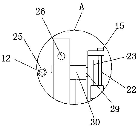
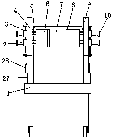
[0036] refer to Figure 1-6 , the two first support frames 19 are provided with a second push rod motor 29 on one side near the mounting hole 26, and the output ends of the two second push rod motors 29 are connected with a second push rod 30, and the two second push rod motors 29 are connected to each other. The other side of the rod 30 is connected with a fixed frame 4, and the two fixed frames 4 are provided with strip-shaped sliding grooves 23, and the insides of the two sliding grooves 23 are equipped with relatively parallel first connecting frames 5, two One end of the first connecting frame 5 is connected to the limit block 3, and the other ends of the two first connecting frames 5 pass through the sliding groove 23, and are provided with a through sliding track 9, and sliding rails 9 are installed inside the two sliding rails 9. Block 11, the tops of the two sliding blocks 11 all extend to the top of the first connecting frame 5, and are connected with the second conn...


PUM


Abstract

The invention discloses an obstetric-gynecology movable support. The obstetric-gynecology movable support comprises a fixed base, a containing groove is formed in one side of the fixed base, the two ends of the inside of the containing are each provided with a first rotating shaft, the other ends of the two first rotating shafts are each rotationally connected with a first supporting frame, firstfixed plates are connected between the two first supporting frames, hinges relatively parallel are connected to the sides, away from the first rotating shafts, of the first fixed plates, and second fixed plate are rotationally connected to the other sides of the hinges. The obstetric-gynecology movable support is reasonable in whole design and compact in layout, and in the using process, when an examination bed support needs to be moved, the obstetric-gynecology movable support can be folded to be fixed, the occupied space of the examination bed support is reduced, and the stability of the examination bed support is reinforced; meanwhile, a patient is examined, the opening angels of the legs of the patient and the height of a containing plate are conveniently adjusted as required, and thesupport has the supporting effect on the legs of the patient, and is more conveniently used.

Description

technical field [0001] The invention relates to the technical field of brackets, in particular to a mobile bracket for obstetrics and gynecology. Background technique [0002] A bracket is a supporting structure. Stents are widely used and can be seen everywhere in work and life, such as camera tripods, heart stents used in the medical field and gynecological examination stents. [0003] Since the patient is generally required to lie on the examination table for examination during the gynecological examination, and most of the current stent structures are relatively simple, there are the following disadvantages in the stent technology used for gynecological examination: [0004] 1. The current examination bed support is large in size, takes up more space, and is relatively bulky overall. When it needs to be moved to different locations for use, it is prone to swaying and cannot be well stabilized, and it is inconvenient to move The phenomenon; [0005] 2. During gynecolog...

Claims


Application Information

Patent Timeline
Patent Type & Authority Applications(China)
IPC IPC(8): A61G13/12
CPCA61G13/1245A61G13/128A61G2200/12A61G2203/70
Inventor 王君
Owner 山东瑞通高分子医疗器械有限公司
Why Eureka
Try Eureka