
Driver modeling method for horizontal/longitudinal motion unified framework

A driver model, longitudinal motion technology, applied in control/regulation systems, motor vehicles, transportation and packaging, etc., can solve problems such as control effect error, and achieve good theoretical guiding significance and application prospects.

Inactive Publication Date: 2018-11-16
JILIN UNIV
View PDF9 Cites 10 Cited by
  • Summary
  • Abstract
  • Description
  • Claims
  • Application Information

AI Technical Summary

Problems solved by technology

However, considering most of the working conditions and the characteristics of the controlled object of the driver model—vehicle, the movement of the vehicle in two directions has coupling characteristics, and considering the movement state of a single direction to design the driver model separately will result in neglecting the movement state of the other direction. The deviation makes its control effect have a large error

Method used


Image

  • Driver modeling method for horizontal/longitudinal motion unified framework
  • Driver modeling method for horizontal/longitudinal motion unified framework
  • Driver modeling method for horizontal/longitudinal motion unified framework

Examples


Embodiment Construction

[0059] The proposed design scheme will be further elaborated and illustrated below in conjunction with the accompanying drawings.

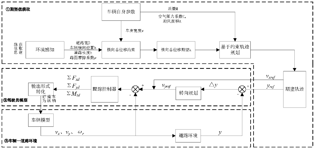
[0060] The present invention proposes a driver model design method in which vehicle lane change trajectory planning and lateral / longitudinal motion are unified for vehicle driving safety, wherein the driver model workflow layer diagram involved is as follows Figure 1 shown.

[0061] Module ① represents the horizontal and vertical expected quantity acquisition module of the driver model. Through the perception of the external environment and the parameters of the vehicle itself, the lateral displacement parameters and the constraint domains of the flatness parameters after the trajectory analysis of the vehicle when the vehicle performs lateral lane change are obtained, and then through the environment and The driving safety requirements and the driver's own characteristics optimize the trajectory parameters to obtain the optimized parameters, and...


PUM


Abstract

A driver modeling method for a horizontal / longitudinal motion unified framework includes the following steps: establishing a vehicle lateral single lane change trajectory analytic expression by usinga hyperbolic tangent function; acquiring road information, vehicle information, and the driving state information of the vehicle; obtaining the constraint of lateral displacement of the vehicle according to road state information; establishing an indicator function according to a driver characteristic and a safety requirement, obtaining an optimized lateral displacement parameter, and calculatingthe lateral force constraint of the vehicle in combination with the vehicle driving state and an environmental factor; obtaining the vehicle trajectory smoothness constraint by using the lateral forceconstraint; establishing an indicator function in combination with the driver characteristic to obtain an optimized value of a smoothness parameter; and finally obtaining an optimized trajectory expectation. With the lateral expectation and the longitudinal velocity as expected values, a driver model describing the horizontal / longitudinal motion unified framework is established to achieve a trajectory tracking purpose.

Description

technical field [0001] The present invention relates to the technical field of intelligent vehicle control, and in particular to a driver model design method based on the analytical expression of lane-changing trajectories based on driving safety and driver characteristics, parameter constraint calculation and optimization, and horizontal / vertical motion. Background technique [0002] Vehicle trajectory planning and driver model modeling occupy an important research position in the field of intelligent driving. Trajectory planning, as the reference output source of driver modeling, is the first guarantee for the safe operation of the vehicle in the entire intelligent driving process. However, most of the current trajectory planning usually considers the smoothness of the route itself as a safety indicator. This approach is too conservative in trajectory planning, and the planned trajectory that ignores the driving characteristics of the driver cannot guarantee the comfort of...

Claims


Application Information

Patent Timeline
IPC IPC(8): G05D1/02
CPCG05D1/0214G05D1/0221G05D1/0223G05D1/0246G05D1/0257G05D1/0276G05D1/0289
Inventor 王德军丁健楠梁晓娜郑强徐鹏王丽华
Owner JILIN UNIV
Learn More