Intelligent locking device and system
What is Al technical title?
Al technical title is built by PatSnap Al team. It summarizes the technical point description of the patent document.
A locking device and intelligent technology, applied in the field of intelligent locks, can solve problems such as poor reliability
Active Publication Date: 2020-10-16
常州电子研究所有限公司
View PDF5 Cites 0 Cited by
Summary
Abstract
Description
Claims
Application Information
AI Technical Summary
This helps you quickly interpret patents by identifying the three key elements:
Problems solved by technology
Method used
Benefits of technology
Problems solved by technology
[0004] In view of this, the object of the present invention is to provide an intelligent locking device and system to alleviate the technical problem of poor reliability of the intelligent locking device in the prior art
Method used
Image
Click on the blue label to locate the original text in one second.
Reading with bidirectional positioning of images and text.
Examples
Embodiment 1
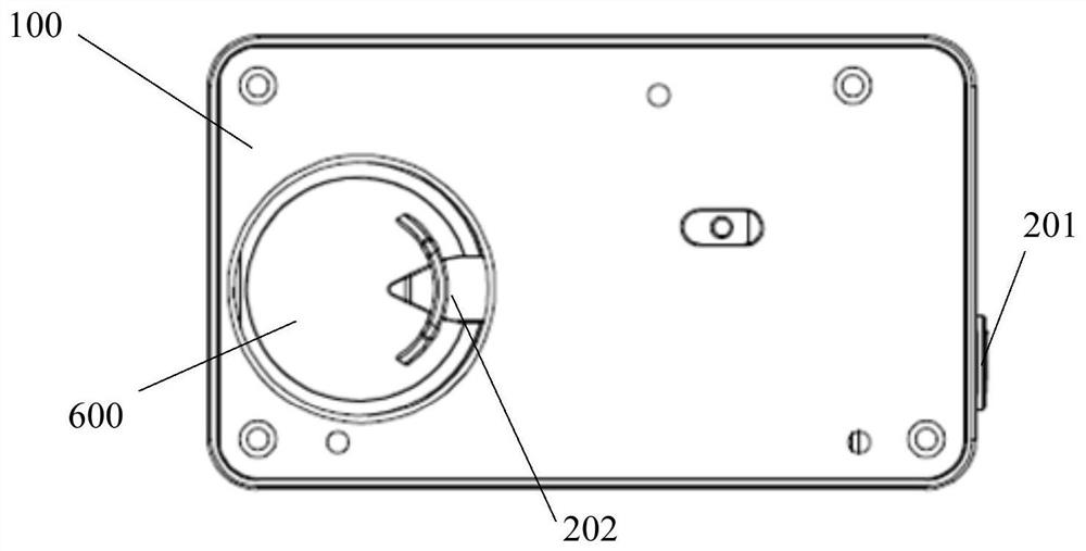
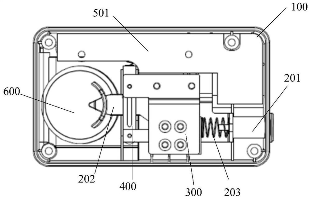
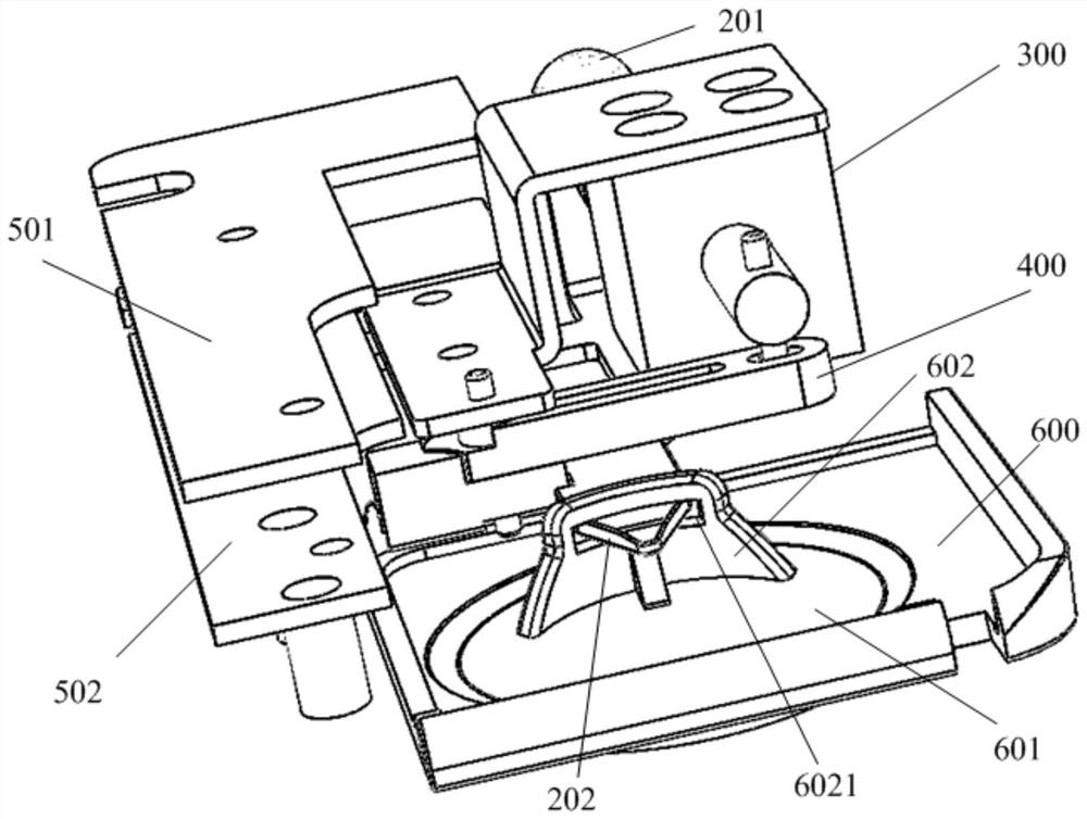
[0034] like Figure 1 to Figure 4 As shown, the embodiment of the present invention provides an intelligent locking device, which can be applied to power equipment, especially a ring main unit of a power system, including: a housing 100, a locking assembly, a driving assembly 300, and a lever assembly 400;
[0035] The locking assembly includes a locking rod 201 and a locking tongue 202; the locking rod is connected with the locking tongue, the top of the locking tongue is connected to the bottom of the locking rod, and the bottom of the locking tongue is used to cooperate with the operation bottom cover 600; the above-mentioned locking rod is arranged on the above-mentioned housing in a telescopic manner, and the above-mentioned locking rod has a tendency to be away from the above-mentioned locking tongue;
[0036] Further, in one embodiment, the locking rod and the locking tongue may be connected in a fixed connection manner such as welding or bonding; in other embodiments, ...
Embodiment 2
[0073] like Figure 5 and Image 6 As shown, the embodiment of the present invention provides an intelligent locking system, including: a key 20 and the intelligent locking device 10 as described in the first embodiment, the key is matched with the intelligent locking device; A battery inside the key case, a switch (also called a power supply button) disposed outside the key case, and a pin 21 disposed outside the key case.
[0074] The housing of the above-mentioned intelligent locking device is provided with a key socket 103 adapted to the above-mentioned pins, and the key is connected to the circuit board of the intelligent locking device through the pins and the key socket.
[0075] Specifically, the casing includes a first casing 101 and a second casing 102, and the first casing and the second casing are connected in a detachable manner, which is convenient for disassembly, maintenance, inspection, replacement of parts, etc.; the casing can play a role in The function o...
PUM
Abstract
The invention provides an intelligent locking device and system, relates to the field of intelligent locks, aims at relieving the problem of poorer reliability existing in an intelligent locking device in the prior art, and can improve the reliability and safety of the intelligent locking device. The device comprises a housing, a locking assembly, a driving assembly and a leverage assembly; the locking assembly comprises a lock jacking rod and a spring bolt; the lock jacking rod is connected with the spring bolt, the top of the spring bolt is connected with the bottom of the lock jacking rod,and the bottom of the spring bolt is used for cooperatively operating a jacking cover; the lock jacking rod can be telescopically arranged on the housing, and the lock jacking rod has the tendency ofgetting away from the spring bolt; the driving assembly is arranged on the housing; the leverage assembly is arranged in the housing, and the leverage assembly is in transmission connection with the driving assembly; when the intelligent locking device is in a locking state, the locking assembly is locked by the leverage assembly; when the intelligent locking device is in an unlocking state, the leverage assembly is separated from the locking assembly.
Description
technical field [0001] The present invention relates to the technical field of intelligent locks, and in particular, to an intelligent locking device and system. Background technique [0002] At present, the existing intelligent locking device usually uses an electromagnet to directly drive the electromagnetic lock tongue to unlock. This method has the following disadvantages: 1. After the electromagnetic lock ejector rod is pressed, it cannot be completely locked, and there is a risk of rebound; 2. In order to provide a larger electromagnetic force, the volume of the electromagnet is usually made larger, so the power consumption is also large. [0003] To sum up, the traditional intelligent locking device has the problem of poor reliability. SUMMARY OF THE INVENTION [0004] In view of this, the purpose of the present invention is to provide an intelligent locking device and system to alleviate the technical problem of poor reliability of the intelligent locking device i...
Claims
Application Information
Patent Timeline
Application Date:The date an application was filed.
Publication Date:The date a patent or application was officially published.
First Publication Date:The earliest publication date of a patent with the same application number.
Issue Date:Publication date of the patent grant document.
PCT Entry Date:The Entry date of PCT National Phase.
Estimated Expiry Date:The statutory expiry date of a patent right according to the Patent Law, and it is the longest term of protection that the patent right can achieve without the termination of the patent right due to other reasons(Term extension factor has been taken into account ).
Invalid Date:Actual expiry date is based on effective date or publication date of legal transaction data of invalid patent.