
Pneumatic ash conveying simulation system

A technology of pneumatic ash conveying and simulation system, which is applied to conveyors, transportation and packaging, conveying bulk materials, etc., can solve the problems of insufficient understanding of the operating conditions of pneumatic ash conveying devices, lack of staff experience, and insufficient practical training. To achieve the effect of easy observation and understanding, good teaching effect, and intuitive display

Inactive Publication Date: 2018-11-16
TAOPU SEWAGE TRAEATMENT PLANT OF SHANGHAI CHENGTOU SEWAGE TREATMENT
View PDF0 Cites 2 Cited by
  • Summary
  • Abstract
  • Description
  • Claims
  • Application Information

AI Technical Summary

Problems solved by technology

At present, due to the continuous operation of the sludge treatment facilities, front-line staff lack of experience, lack of understanding of the internal structure and operating conditions of the pneumatic ash conveying device, and insufficient practical training, resulting in insufficient maintenance capabilities for the pneumatic ash conveying equipment and cannot meet the requirements Sludge Treatment Requirements

Method used


Image

  • Pneumatic ash conveying simulation system

Examples


Embodiment Construction

[0025] The specific embodiments of the present invention will be described in further detail below with reference to the accompanying drawings. These embodiments are only used to illustrate the present invention, but not to limit the present invention.

[0026] In the description of the present invention, it should be noted that the terms "center", "vertical", "horizontal", "upper", "lower", "front", "rear", "left", "right", " The orientation or positional relationship indicated by "vertical", "horizontal", "top", "bottom", "inner", "outer" etc. is based on the orientation or positional relationship shown in the drawings, and is only for the convenience of describing the present invention and simplifying The description does not indicate or imply that the pointed device or element must have a specific orientation, be constructed and operated in a specific orientation, and therefore cannot be understood as a limitation of the present invention. In addition, the terms "first" and ...


PUM


Abstract

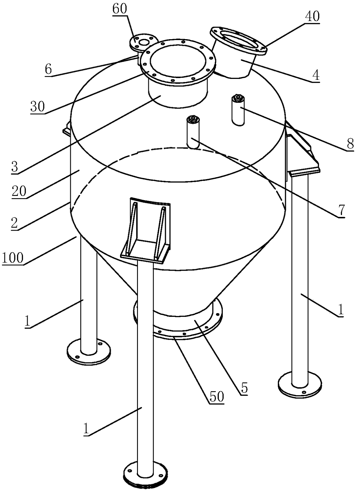
The invention relates to the technical field of sludge treatment equipment simulation training, in particular to a pneumatic ash conveying simulation system. The pneumatic ash conveying simulation system comprises a pneumatic ash conveying model and a control module; the pneumatic ash conveying model comprises a bracket, and a shell supported on the bracket; the shell is transparent, and a cavityis formed inside; a transparent pipeline, communicating with the cavity, is inserted in the shell; a transparent valve is arranged on the transparent pipeline; a first indicating lamp strip for representing a medium is arranged in the transparent pipeline; the first indicating lamp strip is connected with the control module; and the control module controls brightening or extinguishing of the firstindicating lamp strip to demonstrate the flowing direction of the medium and the opening or closing of the valve. The internal structure and the operation working conditions of a pneumatic ash conveying device can be preferably shown; and the advantages of direct displaying, convenience to observe and master and good demonstration effect are achieved.

Description

Technical field [0001] The invention relates to the technical field of simulation training of sludge treatment equipment, in particular to a pneumatic ash transport simulation system. Background technique [0002] With the acceleration of urban development and the continuous maturity of sewage treatment technology, the operating conditions of sewage treatment plants have become increasingly mature and stable. However, while the sewage treatment plant eliminates organic pollution, it also produces a large amount of secondary product-sludge. The problem of sludge treatment and disposal has become increasingly severe. [0003] Pneumatic ash conveying device uses air compressor as the air power source, air as the conveying medium and power, and conveys the fly ash produced by the incineration of sludge in the sludge incinerator through a closed pipeline under high concentration and low flow rate. The device to the fly ash silo is an important equipment in sludge treatment. At presen...

Claims


Application Information

Patent Timeline
Patent Type & Authority Applications(China)
IPC IPC(8): B65G53/66B65G53/34B65G53/52B65G53/46
CPCB65G53/66B65G53/34B65G53/46B65G53/52
Inventor 裘湛张剑峰王荣生姚杰陈沈雷詹晓春
Owner TAOPU SEWAGE TRAEATMENT PLANT OF SHANGHAI CHENGTOU SEWAGE TREATMENT
Learn More