
Active suspension having spiral spring and rubber spring non-concentric with each other

A rubber spring and coil spring technology, applied in elastic suspension, suspension, vehicle spring, etc., can solve the problem of amplifying the ideal control force of the suspension, and achieve the effects of low cost, avoidance of damage and simple structure

Active Publication Date: 2018-11-16
JIANGSU UNIV
View PDF10 Cites 7 Cited by
  • Summary
  • Abstract
  • Description
  • Claims
  • Application Information

AI Technical Summary

Problems solved by technology

[0003] The invention aims at the problem that the ideal control force of the suspension is amplified due to the large equivalent inertial mass of the existing suspension using the rotating motor type active force actuator, and proposes a helical spring and a rubber spring with different axes. The central active suspension, the active force actuator and the coil spring are installed on different axes, and the active force actuator is concentrically connected in series with one or two integral outer ring rubber springs with vibration damping function, which effectively eliminates the impact of the equivalent inertial mass on the ideal The influence of control

Method used


Image

  • Active suspension having spiral spring and rubber spring non-concentric with each other
  • Active suspension having spiral spring and rubber spring non-concentric with each other
  • Active suspension having spiral spring and rubber spring non-concentric with each other

Examples


Embodiment Construction

[0020] Such as figure 1 As shown, the orientation of the present invention is stipulated as follows: the ground is the "down" side, and the coupling assembly 10 is the "up" side; the wheel 14 is rolling on the ground, and the rolling direction of the wheel 14 is the "front and back" direction; Take the wheel 14 on the "outside" side and the bushing 5 on the "inside" side.

[0021] The suspension of the present invention has an active force actuator 9, and the active force actuator 9 is installed between the vehicle body and the wheel 14. The upper end of the active force actuator 9 is fixedly connected to the coupling assembly 10, and the coupling assembly 10 is fixedly connected to the vehicle body.

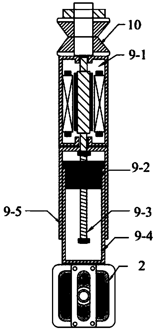
[0022] Such as figure 2 As shown, the outside of the active force actuator 9 is an outer cylinder 9-5, a rotating motor 9-1 and an inner cylinder 9-4 are coaxially sleeved in the outer cylinder 9-5, and balls are coaxially sleeved in the inner cylinder 9-4. Nut 9-2. The hou...


PUM


Abstract

The invention discloses an active suspension having a spiral spring and a rubber spring non-concentric with each other in the technical field of vehicle suspensions. The lower end of an inner cylinderof an active force actuator extends out of an outer cylinder and is concentrically and fixedly connected with a first rubber spring; the first rubber spring consists of a rigid outer ring, a rubber main spring, a rigid guide rail and a rigid inner tube; the spiral spring which is non-concentric with the first rubber spring and the active force actuator is arranged beside the active force actuator; the upper end of the spiral spring is pressed against a connecting plate of a vehicle body; the lower end of the spiral spring is supported on a spring mounting seat fixedly connected to a lower fork arm; the lower fork arm is connected between the vehicle body and a wheel; and the upper end of the outer cylinder of the active force actuator is concentrically and fixedly connected with the lowerend of a rigid outer ring of a second rubber spring whose structure is as same as the structure of the first rubber spring. Except for a primary vibration absorbing function formed by the active force actuator and the spiral spring, the active suspension having the spiral spring and the rubber spring non-concentric with each other also has a secondary vibration absorbing function formed by the first rubber spring and a three-stage vibration absorbing function formed by the second rubber spring.

Description

technical field [0001] The invention belongs to the technical field of vehicle suspension, and in particular relates to a vehicle active suspension adopting a rotating electrical machine type active force actuator. Background technique [0002] The active force actuator is a key component of the vehicle's active suspension. The active force actuator has the ability to provide active control force to the suspension and has the potential to make the car obtain a good ride comfort. At present, active power actuators include hydrostatic type, pneumatic type, linear motor type, ball screw-rotary motor type, hydrostatic-motor / pump-electrical type, etc. Among them, the ball screw-rotary motor type active force actuator is due to The ball screw is used to amplify the movement speed between the suspensions, so its energy density is relatively high, but its disadvantages are: the inertia of the rotating motor rotor is amplified, so that the active control force is connected in paralle...

Claims


Application Information

Patent Timeline
Patent Type & Authority Applications(China)
IPC IPC(8): B60G11/52B60G3/20
CPCB60G3/20B60G11/52B60G2202/14B60G2204/148B60G2800/162B60G2800/20
Inventor 陈士安蒋旭东何仁王骏骋王匀姚明姜顺明
Owner JIANGSU UNIV
Learn More