
PTC automatic mounting device

A technology of automatic installation and installation station, which is applied in the direction of assembly machines, metal processing, metal processing equipment, etc., can solve the problems of difficult extraction and transfer, small size, etc., achieve good operational reliability, reduce space occupation, and overall structure compact effect

Pending Publication Date: 2018-11-16
CHANGSHU TIANYN ELECTROMECHANICAL
View PDF12 Cites 3 Cited by
  • Summary
  • Abstract
  • Description
  • Claims
  • Application Information

AI Technical Summary

Problems solved by technology

However, in the actual automated installation process, since the PTC is button-shaped and relatively small in size, it is difficult to be extracted and transferred to the insertion position for insertion

Method used


Image

  • PTC automatic mounting device
  • PTC automatic mounting device
  • PTC automatic mounting device

Examples


Embodiment Construction

[0038]In order to understand the technical essence and beneficial effects of the present invention more clearly, the applicant will describe in detail the following examples, but the descriptions of the examples are not intended to limit the solutions of the present invention. Equivalent transformations that are only formal but not substantive should be regarded as the scope of the technical solution of the present invention.

[0039] In the following descriptions, all concepts related to the directionality or orientation of up, down, left, right, front and rear are for the position state of the picture being described, so it cannot be understood as Special limitations on the technical solutions provided by the present invention.

[0040] In order to facilitate the understanding of the function of the PTC automatic assembly device of the present invention, the applicant first Figure 5 to Figure 13 to describe.

[0041] See Figure 5 and Figure 6 ,exist Figure 5 and F...


PUM


Abstract

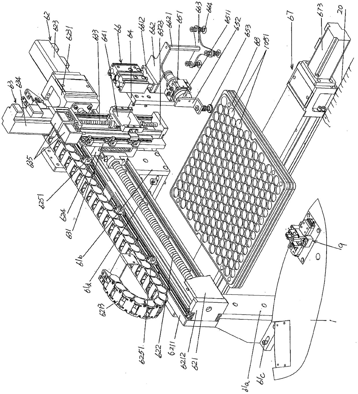
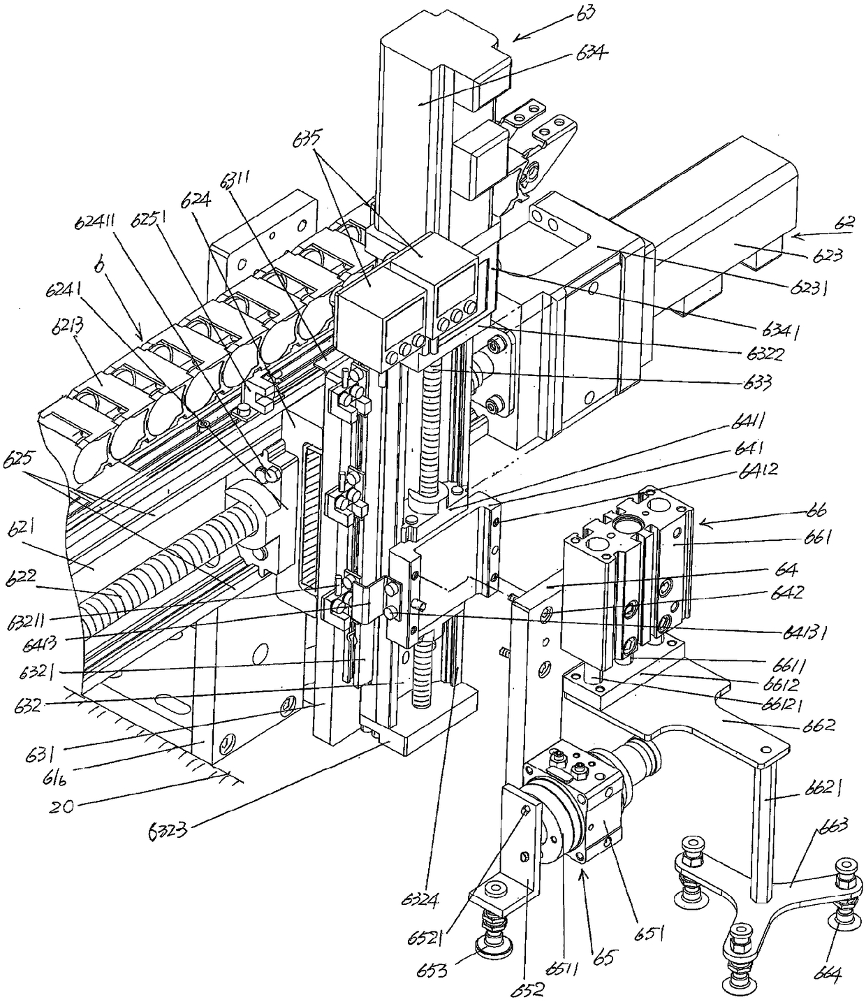
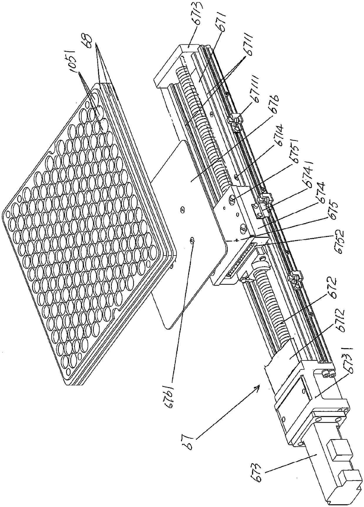
A PTC automatic mounting device comprises a PTC mounting mechanism assembly, which comprises a PTC installation station first bracket, a PTC installation station second bracket, a horizontal displacement device, an up and down displacement device, a lifting platform, a PTC suction device, an empty PTC feeding tray removing device, a PTC feeding tray moving device and a PTC feeding tray, wherein the PTC installation station first bracket and the PTC installation station second bracket are fixed to a worktable, the horizontal displacement device is supported at the tops of the PTC installation station first bracket and the PTC installation station second bracket, the up and down displacement device is connected to the side, facing the PTC feeding tray, of the horizontal displacement device,the lifting platform is connected with the side, facing the PTC feeding tray, of the up and down displacement device, the PTC suction device and the empty PTC feeding tray removing device are arrangedon the side, facing the PTC feeding tray, of the lifting platform, the PTC feeding tray moving device is arranged on the worktable, and the PTC feeding tray is arranged on the PTC feeding tray movingdevice. The automation requirements are met, less space is occupied, and the movement is reliable.

Description

technical field [0001] The invention belongs to the technical field of special facilities for automatic production lines of electronic and electrical products, and in particular relates to a PTC automatic installation device. Background technique [0002] The PTC mentioned above refers to the PTC of the refrigeration compressor motor starter. Taking the common refrigeration compressor motor as an example, because it is a low-power single-phase AC motor, it needs to be started by a starter when starting, and when the compressor enters a normal operating state, it needs to be protected by a protector to ensure refrigeration. When the compressor is overloaded during operation, the power supply is disconnected to avoid damage to the refrigeration compressor due to overheating. [0003] Can be seen all the technical information about refrigeration compressor motor starter in the published Chinese patent literature, as CN2664281Y recommends "motor starter" and CN2664283Y provides...

Claims


Application Information

Patent Timeline
Patent Type & Authority Applications(China)
IPC IPC(8): B23P19/00B23P21/00
CPCB23P19/00B23P19/001B23P21/00
Inventor 赵晓东
Owner CHANGSHU TIANYN ELECTROMECHANICAL
Learn More