Pressure relief device of switch cabinet and switch cabinet

A technology of pressure relief device and switchgear, which is applied in the direction of switchgear, switchgear setting, substation/switch layout details, etc., and can solve problems such as potential safety hazards outside the cabinet

Pending Publication Date: 2018-11-13
QINGDAO TGOOD ELECTRIC
View PDF0 Cites 5 Cited by
  • Summary
  • Abstract
  • Description
  • Claims
  • Application Information

AI Technical Summary

Problems solved by technology

[0003] In related technologies, when the gas in the cabinet is depressurized from the top of the cabinet, the damaged and fallen parts and other objects in the cabinet will often fly out of the top of the cabinet due to excessive pressure, causing safety hazards outside the cabinet

Method used


Image

  • Pressure relief device of switch cabinet and switch cabinet
  • Pressure relief device of switch cabinet and switch cabinet
  • Pressure relief device of switch cabinet and switch cabinet

Examples


Embodiment 1

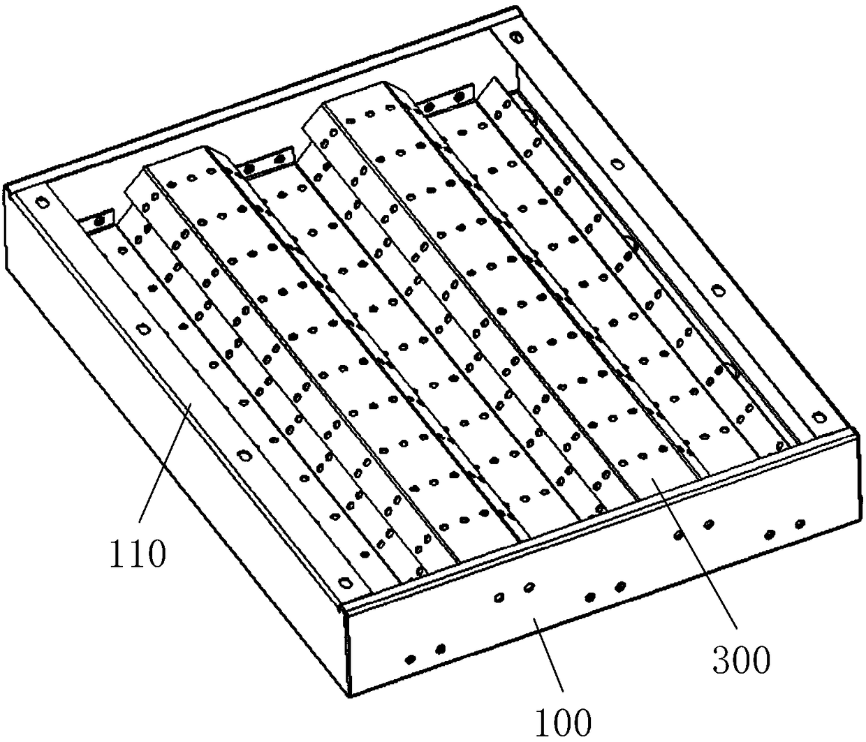
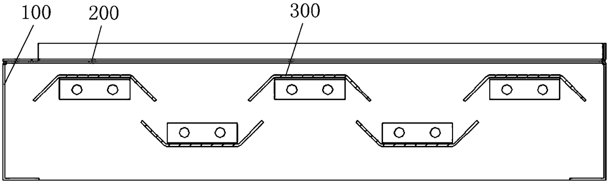
[0033] The switch cabinet pressure relief device provided by the embodiment of the present invention includes: a cabinet top plate 100, a pressure relief plate 200 and a plurality of arc baffles 300, and the opposite sides of the arc baffles 300 have bent edges to form a buffer cavity ;

[0034] The top plate 100 of the cabinet has a pressure relief chamber, the pressure relief chamber runs through the top plate 100 of the cabinet, and a plurality of arc baffles 300 are all arranged in the pressure relief chamber, and arc discharge gaps are left between adjacent arc baffles 300, each The bent edge of the arc baffle 300 is opposite to the buffer cavity of the adjacent arc baffle 300;

[0035] The pressure relief plate 200 covers the pressure relief chamber, the first side of the pressure relief plate 200 is fixedly connected with the top panel 100 of the cabinet, the second side of the pressure relief plate 200 is detachably connected with the top panel 100 of the cabinet, and ...

Embodiment 2

[0056] The second embodiment provides a switchgear to alleviate the technical problem of potential safety hazards in the pressure relief of the switchgear in the related art.

[0057] like Image 6 As shown, the switch cabinet provided by the embodiment of the present invention includes a cabinet body and the above-mentioned switch cabinet pressure relief device. The top of the 430 is equipped with a switch cabinet pressure relief device.

[0058] Further, the pressure relief device of the switch cabinet is connected with the cabinet by bolts.

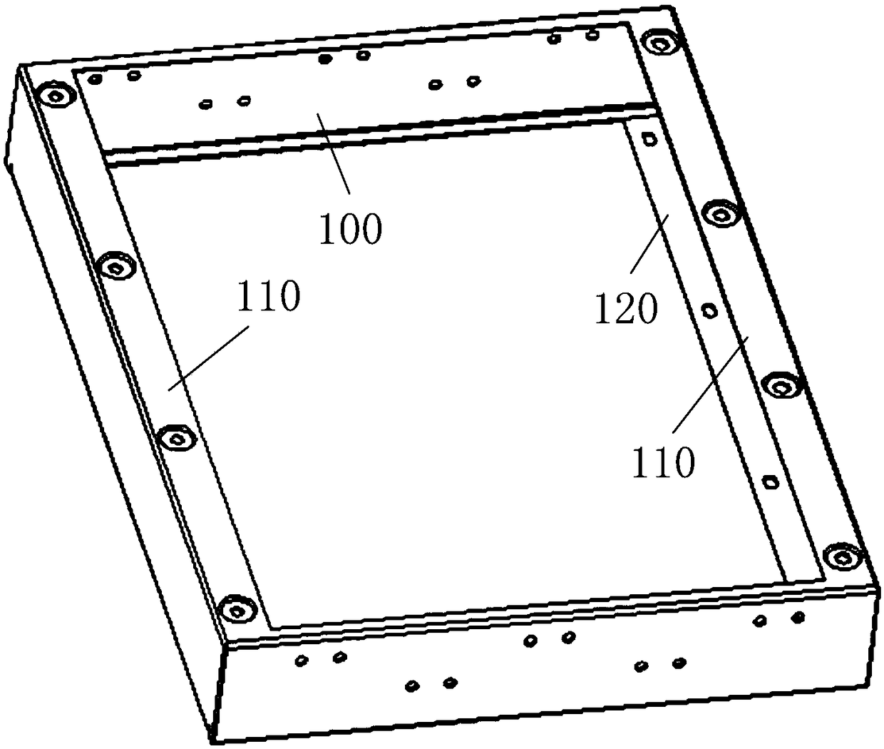
[0059] The second connection plate 120 of the cabinet top plate 100 is provided with a plurality of through holes, and the plurality of through holes are distributed at intervals along the length direction of the second connection plate 120, and the bolts pass through the through holes on the second connection plate 120 and the cabinet. The body thread fits, so that the switchgear pressure relief device is installed on the cabinet bo...


PUM


Abstract

The invention provides a pressure relief device of a switch cabinet and the switch cabinet, and relates to the technical field of electrical equipment. The pressure relief device of the switch cabinetcomprises a cabinet top plate, a pressure relief plate and a plurality of arcing baffles, wherein bent edges are arranged on two opposite sides of each arcing baffle to form a buffer cavity; a pressure relief chamber is formed in the cabinet top plate and penetrates the cabinet top plate, the plurality of arcing baffles are all arranged in the pressure relief chamber, arc relief gaps are left between adjacent arcing baffles, and the bent edges of the arcing baffles are opposite to the buffer cavities of the adjacent arcing baffles; the pressure relief plate covers the pressure relief chamber,the first side edge of the pressure relief plate is fixedly connected with the cabinet top plate, the second side edge of the pressure relief plate is detachably connected with the cabinet top plate,and the first side edge is opposite to the second side edge. The technical problem of potential safety hazards in pressure relief of switch cabinets in related technologies is solved by the pressurerelief device of the switch cabinet.

Description

technical field [0001] The invention relates to the technical field of electrical equipment, in particular to a switch cabinet pressure relief device and a switch cabinet. Background technique [0002] The switch cabinet is a kind of electrical equipment. The outside line of the switch cabinet first enters the main control switch in the cabinet, and then enters the sub-control switch. Each branch is set according to its needs. The main function of the switchgear is to open and close, control and protect electrical equipment during the process of power generation, transmission, distribution and power conversion in the power system. During the operation of the switchgear, due to various reasons (such as short circuit, insulation aging and human error, etc.), a circuit short circuit fault occurs. Under the short circuit current of tens of thousands of amperes, high temperature and high pressure gas is generated instantly. If the high temperature and high pressure gas is in a na...

Claims


Application Information

Patent Timeline
IPC IPC(8): H02B1/30H02B13/025
CPCH02B1/30H02B1/306H02B13/025
Inventor 骆祥华牟洪斌高海峰
Owner QINGDAO TGOOD ELECTRIC
Why Eureka
Try Eureka