
Double-suction double-shaft multi-stage axially split pump system

A pump system and first-level technology, applied to pumps, pump devices, pump components, etc., can solve problems such as high energy consumption and serious water pump cavitation, achieve the goals of reducing output energy consumption, increasing yield, and eliminating hidden dangers of cavitation Effect

Active Publication Date: 2018-11-13
淄博安德泵阀科技有限公司
View PDF5 Cites 2 Cited by
  • Summary
  • Abstract
  • Description
  • Claims
  • Application Information

AI Technical Summary

Problems solved by technology

[0004] The purpose of the present invention is to provide a double-suction, double-shaft, multi-stage split pump system, which effectively solves the problems of serious cavitation and high energy consumption of existing water pumps

Method used


Image

  • Double-suction double-shaft multi-stage axially split pump system

Examples


Embodiment 1

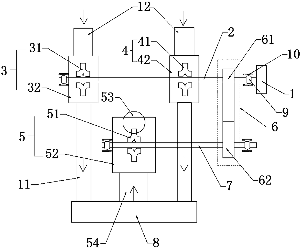
[0039] like figure 1 shown, with figure 1 The direction of the arrow in the figure is the water flow direction when the split pump is working. A double-suction, multi-axis and multi-stage split pump system of the present invention includes the main power source 1, the main transmission shaft 2, the first head water pump 3, the second head pump Primary water pump 4, at least one secondary main water pump 5, transmission gear pair 6 and at least one secondary main transmission shaft 7;

[0040] The main power source 1 provides power for the first primary water pump 3 and the second primary water pump 4 through the main transmission shaft 2;

[0041] The main power source 1 provides power for the secondary main water pump 5 through the main transmission shaft 2, the transmission gear pair 6 and the secondary main transmission shaft 7;

[0042] The first primary water pump 3 and the second primary water pump 4 are respectively connected to the secondary main water pump 5 through...

Embodiment 2

[0054] likefigure 1 As shown, a double-suction, multi-shaft and multi-stage split pump system of the present invention includes a main power source 1, a main transmission shaft 2, a first first-stage water pump 3, a second first-stage water pump 4, and at least one secondary main water pump 5 , transmission gear pair 6 and at least one secondary main transmission shaft 7;

[0055] The main power source 1 provides power for the first primary water pump 3 and the second primary water pump 4 through the main transmission shaft 2;

[0056] The main power source 1 provides power for the secondary main water pump 5 through the main transmission shaft 2, the transmission gear pair 6 and the secondary main transmission shaft 7;

[0057] The first primary water pump 3 and the second primary water pump 4 are respectively connected to the secondary main water pump 5 through external pipes 8 .

[0058] Further, the first first stage water pump 3 includes a first first stage impeller 31 a...


PUM

PropertyMeasurementUnit
Roughnessaaaaaaaaaa

Abstract

The invention discloses a double-suction double-shaft multi-stage axially split pump system. The system comprises a main power source, a main transmission shaft, a first primary water pump, a second primary water pump, at least one secondary main water pump, a transmission gear pair and at least one secondary main transmission shaft. The main power source provides power for the first primary waterpump and the second primary water pump through the main transmission shaft, the main power source provides power for the secondary main water pump through the main transmission shaft, the transmission gear pair and the secondary main transmission shaft, and the first primary water pump and the second primary water pump are connected with the secondary main water pump through an external connection pipeline. The double-suction double-shaft multi-stage axially split pump system is simple in structure and convenient to use, rigidity transmission and variation transmission ratio are achieved, theproblem that a traditional water pump is serious in cavitation is solved, a main output stage hydraulic model can adopt the extremely-high-efficiency hydraulic model due to the negative pressure of the suction stage, the output energy consumption is greatly reduced, and the energy saving effect is achieved.

Description

technical field [0001] The invention relates to the field of split pumps, in particular to a double-suction, double-shaft and multi-stage split pump system. Background technique [0002] Domestically and internationally, several pumps are used to operate in series to achieve high-lift delivery at low speed. This mode of operation will cause a loss of at least 20%, resulting in a large amount of energy consumption. If water is taken from rivers and ditches for irrigation or the water temperature is high, the performance requirements for the NPSH of the water pump are high, and the existing water pumps and single pumps cannot meet the requirements, so a front pump or a front negative pressure device needs to be added. Reliability and convenience are greatly weakened like this. [0003] In order to solve the above problems, it is urgent to invent a double-suction double-shaft multi-stage split pump system to solve the problems of serious cavitation and high energy consumption...

Claims


Application Information

Patent Timeline
IPC IPC(8): F04D13/12F04D29/02F04D29/66F04D29/054
CPCF04D13/12F04D29/026F04D29/054F04D29/669
Inventor 邢涵吉翟鲁涛孙廷泉郭秀红
Owner 淄博安德泵阀科技有限公司
Learn More