


Quick Research
Generate reliable direction feasibility study reports for your R&D in just a few steps.

Technical Q&A
Discover and master advanced knowledge NOW. Basics, ideas, possibilities, all at once.

Find Solutions
As an expert in R&D theories, this can generate solutions to your technical problems instantly.

Evaluate Feasibility
Analyze your overall solution with one click, know your potential R&D risks in advance.

Monitor Landscape
Get weekly tech updates, stay abreast of the latest tech innovations and key insights.
A double-suction double-shaft multi-stage split pump system
A pump system and first-stage technology, applied in the direction of pumps, pump components, pump devices, etc., can solve the problems of serious cavitation and high energy consumption of water pumps, and achieve the effects of reducing output energy consumption, improving yield, and achieving energy-saving effects.
- Summary
- Abstract
- Description
- Claims
- Application Information
AI Technical Summary
Problems solved by technology
Method used
Image

Examples
Embodiment 1
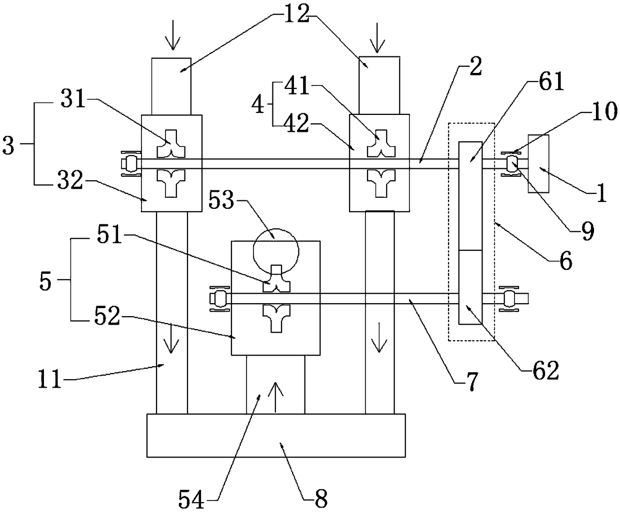
[0038] Such as figure 1 shown, with figure 1 The direction of the arrow in the figure is the water flow direction when the split pump is working. A double-suction, multi-axis and multi-stage split pump system of the present invention includes the main power source 1, the main transmission shaft 2, the first head water pump 3, the second head pump Primary water pump 4, at least one secondary main water pump 5, transmission gear pair 6 and at least one secondary main transmission shaft 7;
[0039] The main power source 1 provides power for the first primary water pump 3 and the second primary water pump 4 through the main transmission shaft 2;
[0040] The main power source 1 provides power for the secondary main water pump 5 through the main transmission shaft 2, the transmission gear pair 6 and the secondary main transmission shaft 7;
[0041] The first primary water pump 3 and the second primary water pump 4 are respectively connected to the secondary main water pump 5 thro...
Embodiment 2
[0053] Such as figure 1As shown, a double-suction, multi-shaft and multi-stage split pump system of the present invention includes a main power source 1, a main transmission shaft 2, a first first-stage water pump 3, a second first-stage water pump 4, and at least one secondary main water pump 5 , transmission gear pair 6 and at least one secondary main transmission shaft 7;
[0054] The main power source 1 provides power for the first primary water pump 3 and the second primary water pump 4 through the main transmission shaft 2;
[0055] The main power source 1 provides power for the secondary main water pump 5 through the main transmission shaft 2, the transmission gear pair 6 and the secondary main transmission shaft 7;
[0056] The first primary water pump 3 and the second primary water pump 4 are respectively connected to the secondary main water pump 5 through external pipes 8 .
[0057] Further, the first first stage water pump 3 includes a first first stage impeller ...
PUM
 Abstract
Description
Claims
Application Information
 - R&D Engineer
- R&D Manager
- IP Professional
- Industry Leading Data Capabilities
- Powerful AI technology
- Patent DNA Extraction
Browse by: Latest US Patents, China's latest patents, Technical Efficacy Thesaurus, Application Domain, Technology Topic, Popular Technical Reports.
© 2024 PatSnap. All rights reserved.Legal|Privacy policy|Modern Slavery Act Transparency Statement|Sitemap|About US| Contact US: help@patsnap.com