Optical fiber twisting equipment

An optical fiber and uniform technology, applied in the field of optical fiber twisting device, can solve the problems of economic loss, complex and bulky twisting equipment, etc., and achieve the effect of simple structure, easy adjustment and maintenance, and stable control of polarization mode dispersion

Pending Publication Date: 2018-11-13
ZHONGTIAN TECH FIBER OPTICS +1
View PDF0 Cites 0 Cited by
  • Summary
  • Abstract
  • Description
  • Claims
  • Application Information

AI Technical Summary

Problems solved by technology

However, no matter whether the twisting equipment adopts double-wheel rubbing or single-wheel rubbing, it will squeeze the surface of the optical fiber and cause different degrees of surface damage, which will bring certain economic losses; in addition, the twisting equipment is relatively complicated. , bulky, not easy to adjust and maintain

Method used


Image

  • Optical fiber twisting equipment
  • Optical fiber twisting equipment
  • Optical fiber twisting equipment

Examples


Embodiment 1

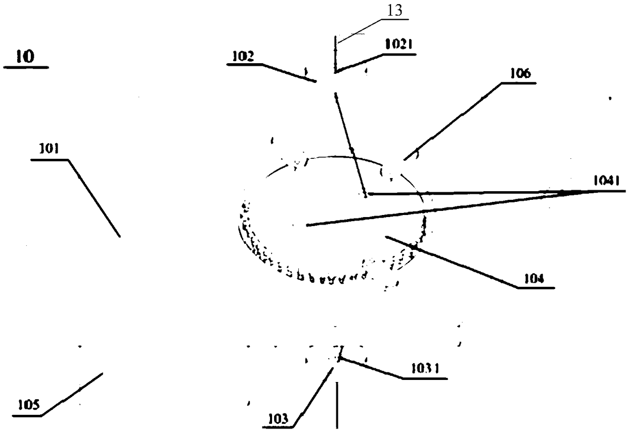
[0046] refer to figure 2 as shown, figure 2 It is a schematic diagram of a three-dimensional structure of an optical fiber twisting device provided by an embodiment of the present invention. The fiber twisting device 10 includes a base frame 101 , a first limiting member 102 , a second limiting member 103 , a rotating disk 104 and a driving assembly 105 .

[0047] Specifically, the base frame 101 has a cylindrical hollow structure, the rotating disk 104 is erected on the top of the hollow structure, and the first limiting member 102 and the second limiting member 103 are symmetrically arranged on the upper and lower sides of the rotating disk 104; The distance between the limiting member 102 , the second limiting member 103 and the rotating disk 104 can be adjusted. Wherein, the first limiting member 102 and the second limiting member 103 can be respectively fixed on a supporting structure (not shown), and the supporting structure can be fixed on the base frame 101 .

[0...

Embodiment 2

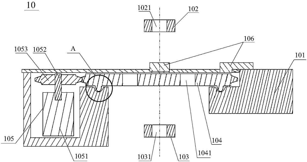
[0067] refer to Figure 8 as shown, Figure 8 It is a schematic cross-sectional structure diagram of an optical fiber twisting device provided by an embodiment of the present invention. The fiber twisting device includes a fiber twisting device 10 including a first limiting member 102 , a second limiting member 103 , a rotating disk 104 and a driving assembly 105 .

[0068] Specifically, the first limiting member 102 and the second limiting member 103 are symmetrically arranged on the upper and lower sides of the edge of the rotating disk 104; the distance between the first limiting member 102, the second limiting member 103 and the rotating disk 104 adjustable. Wherein, the first limiting member 102 and the second limiting member 103 may be respectively fixed on a supporting structure (not shown).

[0069] The first stopper 102 is provided with a first through hole 1021 for the introduction of the optical fiber 13, the second stopper 103 is provided with a second through h...


PUM


Abstract

The invention discloses an optical fiber twisting equipment, and belongs to the technical field of optical fiber manufacturing. The optical fiber twisting equipment includes a rotating disc and a first limit member and a second limit member which are symmetrically arranged over and below the rotating disc. The first limit member is provided with a first through hole for introducing an optical fiber, and the second limit member is provided with a second through hole for leading the optical fiber out. The rotating disc is provided with at least a pair of third through holes which are symmetricalwith each other relative to the center of the rotating disc. The optical fiber passes through one of the third through holes. The first through hole, the second through hole and the third through holes are provided with smooth inner walls. The optical twisting device is provided with a driving assembly. The rotating disc rotates around the center of the rotating disc driven by the driving assembly so as to twist the optical fiber. The optical fiber twisting device provided by the invention can reduce polarization mode dispersion, can avoid damages to the surface of the optical fiber, and is simple in structure and convenient in adjustment and maintenance.

Description

technical field [0001] The invention relates to the technical field of optical fiber manufacturing, in particular to an optical fiber twisting device. Background technique [0002] Polarization Mode Dispersion refers to the polarization dispersion in single-mode fiber, referred to as PMD (Polarization Mode Dispersion), which is the dispersion caused by the tiny asymmetry of the cross-section of the fiber. speed spread. If the polarization mode dispersion is large, it will cause waveform degradation in the signal light transmitted in the optical fiber, making it difficult to separate adjacent pulses and causing problems such as limited transmission capacity. Therefore, it is desirable to suppress the polarization mode dispersion as small as possible . In addition, the main factor of the slight asymmetry of the cross-section of the optical fiber is that the cross-sectional shape of the optical fiber is an elliptical cross-section. In the case of a method of manufacturing a ...

Claims


Application Information

Patent Timeline
Patent Type & Authority Applications(China)
IPC IPC(8): C03B37/03
CPCC03B37/03
Inventor 田文远耿培恒曹珊珊王震徐海涛刘志忠薛济萍薛驰
Owner ZHONGTIAN TECH FIBER OPTICS
Why Eureka
Try Eureka