Back-thrust-force-free type composite wing manned craft with turbofan thrust composite auxiliary wings

A composite wing and aircraft technology, applied in the field of aircraft, can solve the problems of low wing structure strength, slow horizontal flight speed, and unsatisfactory controllability, and achieves expansion of wing area, fast flight speed, and convenient cluster flight. Effect

Inactive Publication Date: 2018-11-13
JIANGSU CHANGTAN ROBOT CO LTD
View PDF4 Cites 0 Cited by
  • Summary
  • Abstract
  • Description
  • Claims
  • Application Information

AI Technical Summary

Problems solved by technology

The traditional fixed wing has the advantages of fast flight speed, low energy consumption, etc., but it has the disadvantages that the main wing and the horizontal tail are not connected front and rear, the wing structure is not strong, easy to be damaged, the take-off and landing requirements are high, and the take-off and landing distance is long; the traditional vertical The take-off and landing aircraft has the advantages of convenient take-off and landing, but has the disadvantages of high energy consumption, low safety factor, poor load capacity, slow horizontal flight speed, and easy crash; although the current vertical take-off and landing fixed wing has the characteristics of convenient take-off and landing , but the controllability is not ideal when flying horizontally, and there are disadvantages such as large flight resistance, high energy consumption, and low safety factor.

Method used


Image

  • Back-thrust-force-free type composite wing manned craft with turbofan thrust composite auxiliary wings
  • Back-thrust-force-free type composite wing manned craft with turbofan thrust composite auxiliary wings
  • Back-thrust-force-free type composite wing manned craft with turbofan thrust composite auxiliary wings

Examples


Embodiment Construction

[0029] The present invention will be further described below in conjunction with the accompanying drawings.

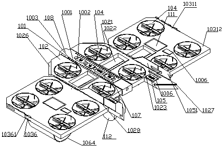
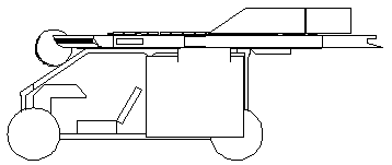
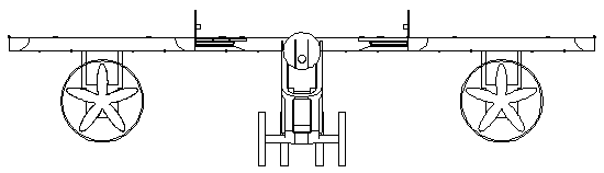
[0030] Such as Figure 1 to Figure 5 Shown, a kind of non-rear-thrust type compound wing manned aircraft with turbofan push compound auxiliary wing is characterized in that, is self-supplied by the thrust of the non-rear-thrust type compound wing manned aircraft and the turbofan that is assembled on both sides of its wing It can be composed of composite auxiliary wings; wherein, the non-rear thrust type composite wing manned aircraft includes a body 101, and a composite lift wing 102 fixedly installed on both sides of the body 101; wherein, wherein, the body 101 is set as a deck platform The self-enclosed ducted fan 104 is built into the described composite lift wing 102, and the outside of the composite lift wing 102 is designed with a wing hinge (1028); 1064, a self-enclosed ducted fan 104 is provided inside the turbofan thrust self-powered composite aileron, and an...


PUM


Abstract

The invention provides a back-thrust-force-free type composite wing manned craft with turbofan thrust composite auxiliary wings. The back-thrust-force-free type composite wing manned craft comprises acraft body and composite elevating force wings fixedly mounted on the two sides of the craft body. The craft body is arranged to be a deck platform. The composite elevating force wings are internallyprovided with self-sealing ducted fans, and wing hinges are designed on the outer sides of the composite elevating force wings. Turbofan thrusters are arranged at the front ends of turbofan thrust self-powered composite auxiliary wings, electricity, liquid and gas interfaces and the wing hinges are arranged on one sides or two sides of the turbofan thrust self-powered composite auxiliary wings, and the turbofan thrust self-powered composite auxiliary wings are connected with the composite elevating force wings through the wing hinges. The back-thrust-force-free type composite wing manned craft has the characteristics of being short in take-off and landing distance, high in flight speed, high in wing structure strength, capable of achieving energy storage through the wings, low in flight energy consumption, long in hovering time, high in safety and the like, the auxiliary wings adopt composite elevating force, and the adaptability of power is guaranteed.

Description

technical field [0001] The invention relates to an aircraft, in particular to a non-rear thrust compound wing manned aircraft with a turbofan thrust compound auxiliary wing, which belongs to the technical field of aircraft equipment. Background technique [0002] Existing aircraft are mainly divided into two categories: fixed-wing and vertical take-off and landing aircraft (such as helicopters and multi-rotors). Of course, there is also a vertical take-off and landing fixed-wing product. The traditional fixed wing has the advantages of fast flight speed, low energy consumption, etc., but it has the disadvantages that the main wing and the horizontal tail are not connected front and rear, the wing structure is not strong, easy to be damaged, the take-off and landing requirements are high, and the take-off and landing distance is long; the traditional vertical The take-off and landing aircraft has the advantages of convenient take-off and landing, but has the disadvantages of...

Claims


Application Information

Patent Timeline
Patent Type & Authority Applications(China)
IPC IPC(8): B64C27/22B64C27/20B64C3/00B64C1/00B64C9/00
Inventor 任曲波
Owner JIANGSU CHANGTAN ROBOT CO LTD
Why Eureka
Try Eureka