Permanent magnetic direct drive bogie and railway vehicle thereof

A permanent magnet direct drive, bogie technology, applied in the field of rail vehicles, can solve the problems of high traction point, permanent magnet motor, not suitable for high-speed locomotives, etc., to reduce the failure rate, prolong the service life, and eliminate the problem of lubrication and sealing Effect

Active Publication Date: 2018-11-13
ZHUZHOU ELECTRIC LOCOMOTIVE CO LTD
View PDF9 Cites 9 Cited by
  • Summary
  • Abstract
  • Description
  • Claims
  • Application Information

AI Technical Summary

Problems solved by technology

However, the suspension adopts rigid suspension, and the permanent magnet motor suspension is not decoupled, so the vibration during operation will have an excessive impact on the permanent magnet motor
[0008] In addition, the existing permanent magnet direct drive bogie has a high traction point, which is not suitable for high-speed locomotives under the condition of high power and large traction force

Method used


Image

  • Permanent magnetic direct drive bogie and railway vehicle thereof
  • Permanent magnetic direct drive bogie and railway vehicle thereof
  • Permanent magnetic direct drive bogie and railway vehicle thereof

Examples


Embodiment 1

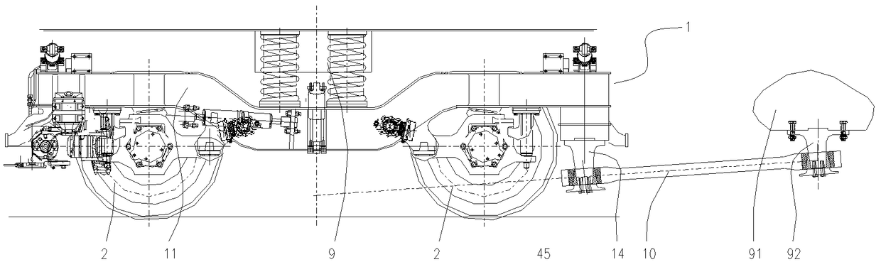
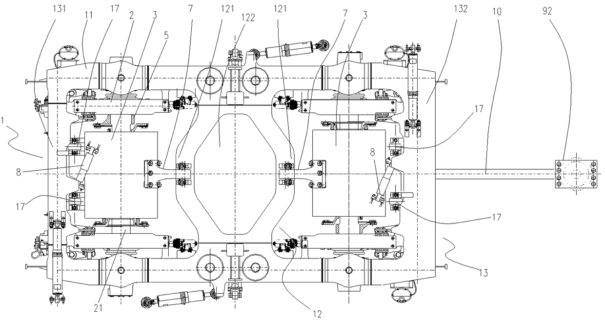
[0047] Such as Figure 1~2. As shown in 6-7, a permanent magnet direct drive bogie includes a frame 1 , a wheel set 2 arranged on the frame 1 , and a permanent magnet motor 3 . The frame 1 includes a longitudinal beam 11 , a cross beam 12 perpendicular to the longitudinal beam 11 , and end beams 13 arranged at two ends of the longitudinal beam 11 . The end beam 13 is divided into a front end beam 131 and a rear end beam 132 . A through hole 122 is defined in the middle of the beam 12 .

[0048] A hollow shaft 4 is sleeved on the axle shaft 21 of the wheel set 2 . A force transmission seat 5 is fixedly arranged on the axle shaft 21 . The permanent magnet motor 3 is sleeved on the hollow shaft 4 . One end of the hollow shaft 4 is connected to the permanent magnet motor 3 through a flexible coupling 6 , and the other end of the hollow shaft 4 is connected to the force transmission seat 5 through a flexible coupling 3 . The flexible coupling 6 is a lamination coupling. The l...

Embodiment 2

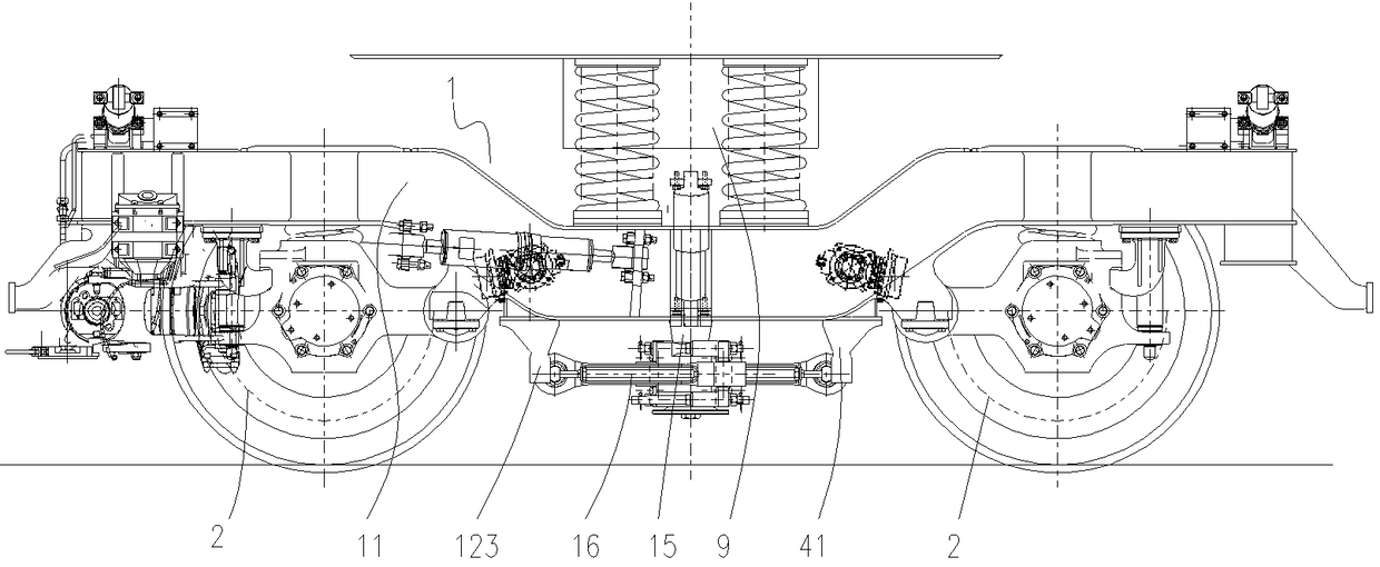
[0054] Such as Figure 3-7 As shown, a permanent magnet direct drive bogie includes a frame 1 , a wheel set 2 arranged on the frame 1 , and a permanent magnet motor 3 . The frame 1 includes a longitudinal beam 11 , a cross beam 12 perpendicular to the longitudinal beam 11 , and end beams 13 arranged at two ends of the longitudinal beam 11 . The end beam 13 is divided into a front end beam 131 and a rear end beam 132 . A through hole 122 is defined in the middle of the beam 12 .

[0055] A hollow shaft 4 is sleeved on the axle shaft 21 of the wheel set 2 . A force transmission seat 5 is fixedly arranged on the axle shaft 21 . The permanent magnet motor 3 is sleeved on the hollow shaft 4 . One end of the hollow shaft 4 is connected to the permanent magnet motor 3 through a flexible coupling 6 , and the other end of the hollow shaft 4 is connected to the force transmission seat 5 through a flexible coupling 3 .

[0056] In this embodiment, the flexible coupling 6 is preferab...


PUM


Abstract

The invention discloses a permanent magnetic direct drive bogie. The permanent magnetic direct drive bogie comprises a framework, a wheel set and a permanent magnetic motor. A hollow shaft is mountedon an axle of the wheel set in a sleeving mode, wherein a force transferring seat is fixedly arranged on the axle, the permanent magnetic motor is mounted on the hollow shaft in a sleeving mode, one end of the hollow shaft is connected with the permanent magnetic motor through a flexible coupling in a binding mode, and the other end of the hollow shaft is connected with the force transferring seatthrough the flexible coupling in a binding mode. Protrusions are arranged on two sides of a beam in the longitudinal direction. The permanent magnetic motor is flexibly connected with the framework through a swing rod and a hanger rod, wherein one end of the swing rod hangs on the protrusions, the other end of the swing rod is connected to a permanent magnetic motor shell, and the axial directionof the swing rod is arranged longitudinally. One end of the hanger rod is connected with the permanent magnetic motor shell, the other end of the hanger rod hangs on an end beam, and the permanent magnetic motor can move horizontally. Through the structural shape of the framework is improved, a hanging structure of the permanent magnetic motor is cooperated, the coordinated application of frame hang installation, low traction and a coupling, and the permanent magnetic motor as a power source to drive high-speed locomotive becomes possible.

Description

technical field [0001] The invention belongs to the field of rail vehicles, and in particular relates to a permanent magnet direct drive bogie and a rail vehicle thereof. Background technique [0002] At present, the high-speed locomotives at home and abroad all adopt the drive system with gear transmission, which has the problems of complex structure, large transmission loss and low reliability, especially the problem of lubrication and sealing during high-speed operation is difficult to solve. At the same time, there are also problems such as high noise and high maintenance costs. [0003] With the advancement of permanent magnet motor technology, the application of direct drive in rail vehicles is also increasing. At present, permanent magnet direct drive is mainly used in light rail vehicles with independent rotating wheels. The main form is wheel hub direct drive or wheel edge direct drive, both of which are directly driven by permanent magnet motors to rotate the whee...

Claims


Application Information

Patent Timeline
Patent Type & Authority Applications(China)
IPC IPC(8): B61C9/50B61F5/00B61F5/52
CPCB61C9/50B61F5/00B61F5/52B61F5/06B61F5/24B61C9/44B61F3/04B61F5/301
Inventor 陈国胜沈龙江易兴利肖泽桦谢加辉王志明蔡超
Owner ZHUZHOU ELECTRIC LOCOMOTIVE CO LTD
Why Eureka
Try Eureka