Central cross beam type traction device

The technology of a traction device and a beam is applied in the field of traction devices, which can solve the problems of increasing the energy consumption of longitudinal traction force transmission, affecting the comfort of passengers riding on rail vehicles, and cumbersome parts maintenance process, so as to improve the adhesion utilization rate, reliable transmission, and convenience. The effect of overhaul

Active Publication Date: 2011-04-20
CRRC QINGDAO SIFANG CO LTD
View PDF0 Cites 0 Cited by
  • Summary
  • Abstract
  • Description
  • Claims
  • Application Information

AI Technical Summary

Problems solved by technology

[0004] Due to the large mass of the bogie, the bogie structure using the bolster traction method is also relatively complex, which brings cumbersome parts maintenance process and increases the energy consumption in the process of longitudinal traction transmission
Especially when running at high speed, the components between the traction devices are noisy, which affects the comfort of passengers on rail vehicles

Method used


Image

  • Central cross beam type traction device
  • Central cross beam type traction device
  • Central cross beam type traction device

Examples


Embodiment 1

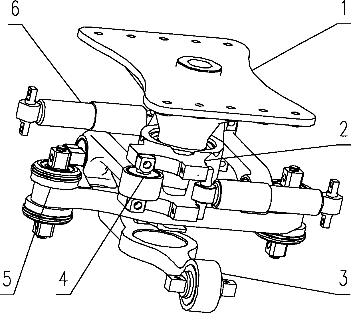
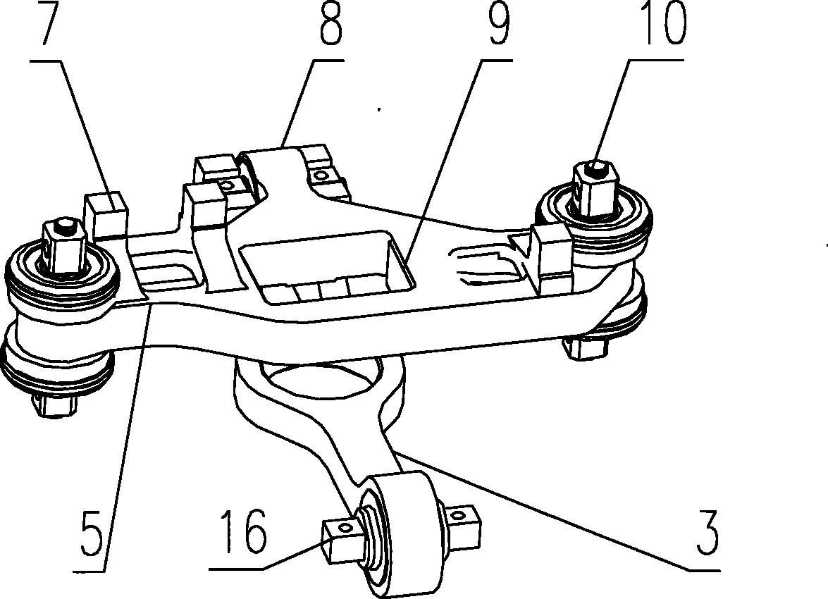
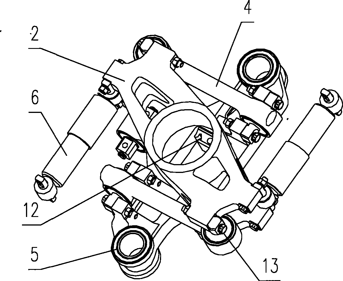
[0038] Example 1, such as Figure 1 to Figure 6 As shown, the central beam type traction device has a traction beam 2 , a longitudinal traction rod 3 , a traction rod 4 , and a central beam 5 . in,

[0039] Both ends of the central beam 5 are connected to the side beams of the bogie frame through elastic nodes 10 . The elastic node 10 is an integral structure made of rubber and metal vulcanized, which can provide the stiffness required by the design. By optimizing the longitudinal stiffness, the transmission of vibration between the traction device as a whole and the frame can be alleviated.

[0040] A longitudinal tie rod seat 8 for connecting the longitudinal pull rod 3 is arranged on the side of the central beam 5 . The longitudinal traction rod 3 has a pull rod body 15, and is connected to the linear motor through a traction joint 16 composed of metal and rubber at its end.

[0041] Two traction rod seats 7 for connecting the traction rods 4 are arranged on the central ...


PUM


Abstract

The invention relates to a central cross beam type traction device. The central cross beam type traction device replaces the swing bolster transmission structure in the prior art, and can effectively reduce the entire weight of a steering frame, simplify the traction structure to be convenient for repair, reduce the energy consumption in the transmission process of longitudinal traction force, andcontrol and reduce the generation of running noise. The central cross beam type traction device is provided with a central cross beam for connecting framework side beams on two sides, the side part of the central cross beam is provided with a base of a longitudinal pulling rod connected with a longitudinal traction rod, and the longitudinal traction rod is connected with a linear motor. The central cross beam is provided with a base of a traction pulling rod, which is used for connecting with the traction pulling rod, and the traction pulling rod is connected with a traction beam. A central pin upwardly connected with a vehicle body is respectively connected with a traction beam and the central cross beam in penetration. The longitudinal traction force is directly transmitted to the central cross beam by the linear motor through the longitudinal traction rod, and the traction beam through the traction pulling rod, and the traction beam transmits the longitudinal traction force to thevehicle body through the central pin to realize the purpose of driving the vehicle body by the linear motor.

Description

technical field [0001] The invention relates to a traction device for rail vehicle bogies, belonging to the field of mechanical manufacturing. Background technique [0002] The linear motor bogies currently used in rail vehicles generally adopt a bolster structure to transmit the longitudinal traction force transmitted from the linear motor to the vehicle body. The traction force of the linear motor is transmitted to the frame through the longitudinal drawbar, then to the bolster through the drawbar, and finally to the car body through the central pin. [0003] The braking force is transmitted to the frame by the wheel set, then to the bolster, and finally to the car body through the center pin. , [0004] Due to the large mass of the bogie, the bogie structure using the bolster traction method is also relatively complicated, which brings cumbersome parts maintenance process and increases the energy consumption in the process of longitudinal traction transmission. Especia...

Claims


Application Information

Patent Timeline
Patent Type & Authority Patents(China)
IPC IPC(8): B61F5/02
Inventor 宋晓文李言义马利军张洪
Owner CRRC QINGDAO SIFANG CO LTD
Why Eureka
Try Eureka