
Spring with limiting function

A function and box technology, applied in the direction of spring, spring/shock absorber, spring/shock absorber design characteristics, etc., can solve the problems of no limit block, spring deformation, and speed up the service life of spring, so as to ensure the use of Longevity, ensure normal cooperation, and avoid deformation and damage

Pending Publication Date: 2018-11-09
江苏省溧水弹簧厂(普通合伙)
View PDF0 Cites 0 Cited by
  • Summary
  • Abstract
  • Description
  • Claims
  • Application Information

AI Technical Summary

Problems solved by technology

[0005] Aiming at the deficiencies of the prior art, the present invention provides a spring with a limiting function, which solves the problem that most of the existing springs do not have the function of a limiting block, and they can be pressed to the bottom to reach the maximum limit. The squeeze of time can easily deform the spring, resulting in damage to the spring, thus speeding up the service life of the spring

Method used


Image

  • Spring with limiting function
  • Spring with limiting function
  • Spring with limiting function

Examples


Embodiment Construction

[0026] The technical solutions in the embodiments of the present invention will be clearly and completely described below in conjunction with the accompanying drawings in the embodiments of the present invention. Obviously, the described embodiments are only a part of the embodiments of the present invention, rather than all the embodiments. Based on the embodiments of the present invention, all other embodiments obtained by those of ordinary skill in the art without creative work shall fall within the protection scope of the present invention.

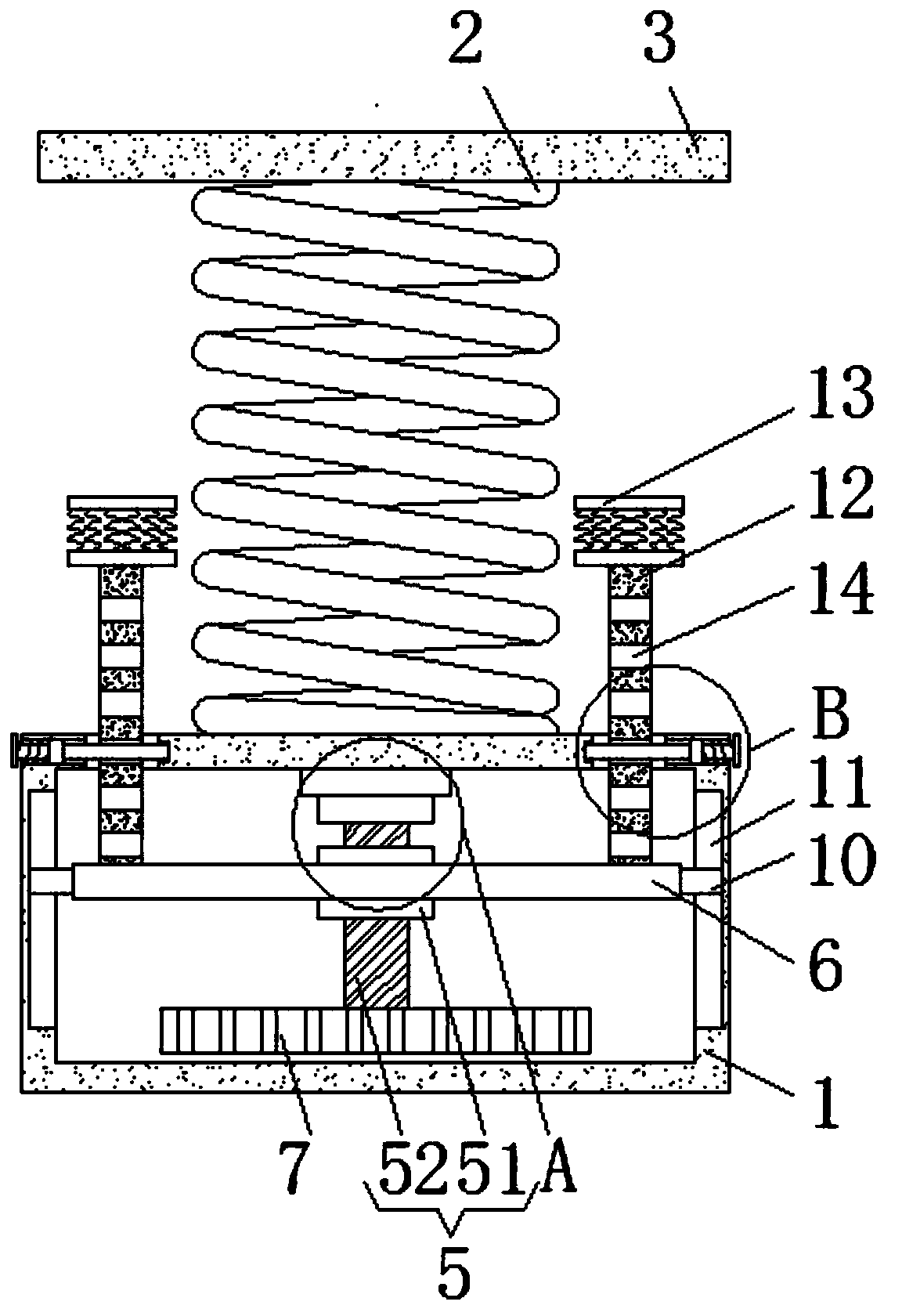
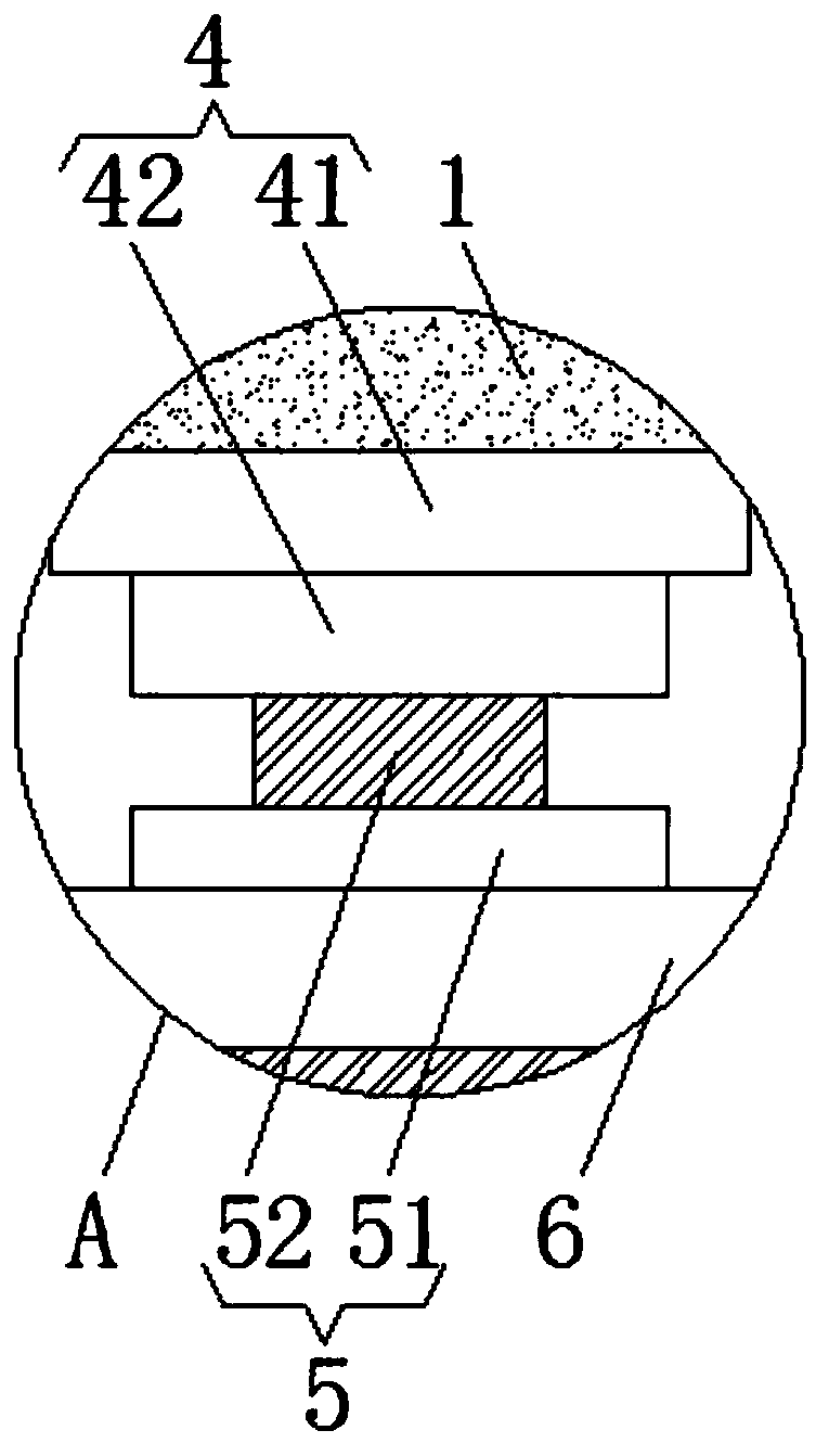
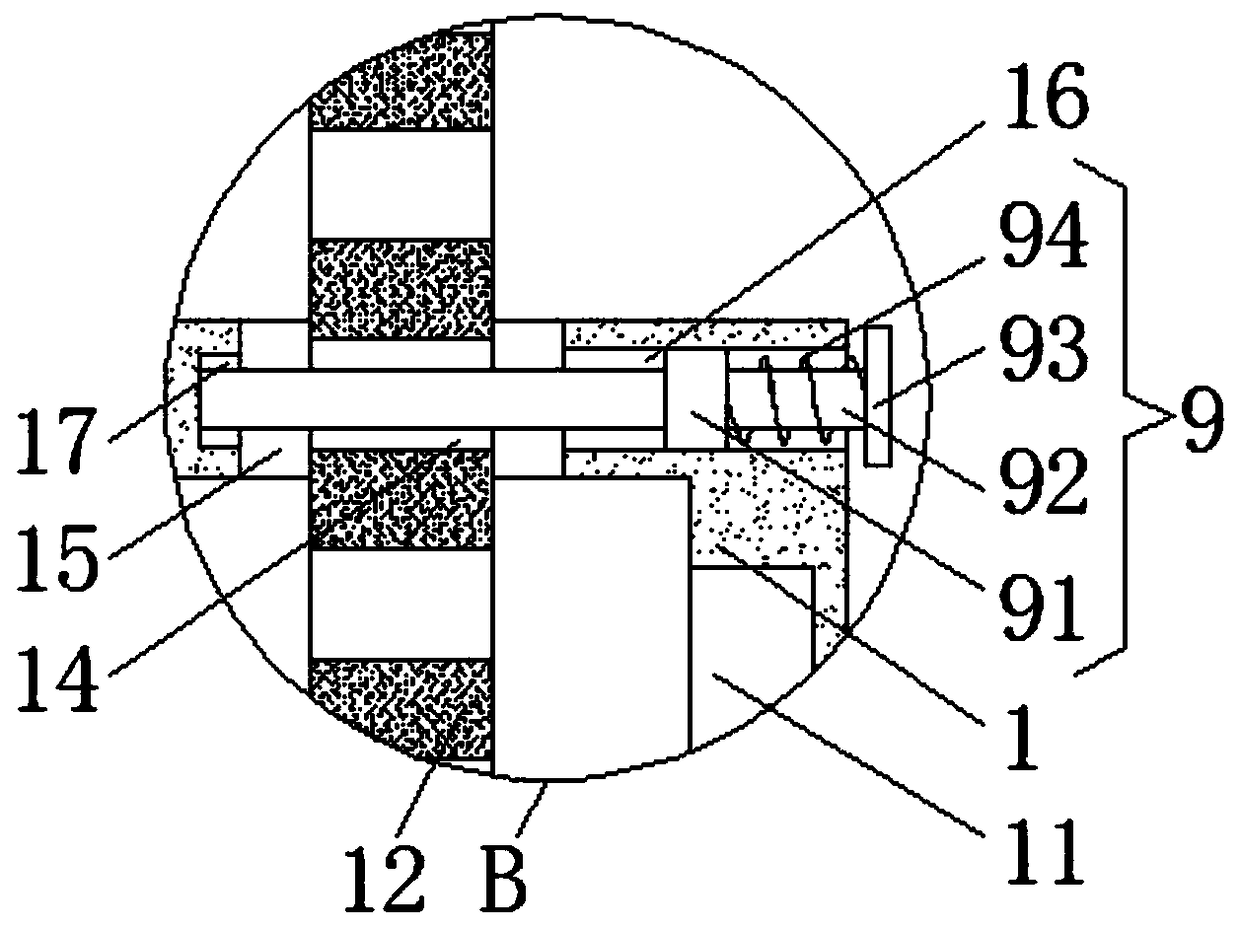
[0027] Such as Figure 1-6 As shown, the present invention provides a technical solution: a spring with a limiting function, comprising a box body 1, the upper surface of the box body 1 is fixedly connected with the lower surface of the top plate 3 through the spring body 2, and the lower surface of the inner wall of the box body 1 The rotating device 4 is clamped on the surface. The rotating device 4 includes a bearing 41. The bearing 4...


PUM


Abstract

The invention discloses a spring with a limiting function. The spring comprises a box body, the upper surface of the box body is fixedly connected with the lower surface of a top plate through a spring body, a rotating device is connected with the lower surface of the inner wall of the box body in a clamped mode, and the bottom end of the rotating device is fixedly connected with the top end of adriving device; and the bottom end of the driving device is fixedly connected with a gear, the driving device is connected with the upper surface of a movable plate in a clamped mode, sliding blocks are fixedly connected to the left side face and the right side face of the movable plate correspondingly, moreover, the two sliding blocks are slidably connected in two sliding grooves respectively, and the two sliding grooves are respectively formed in the left side face and the right side face of the inner wall of the box body. The spring with the limiting function avoids the situation that the spring body is damaged due to deformation in the use of a long time is avoided through the cooperation among the gear, a threaded column, a threaded cap, the movable plate, a rotating shaft, a bearing,the sliding grooves, the sliding blocks, a fixing rod, a sliding rod, a sliding sleeve, the spring and a groove, so that the service life of the spring body is guaranteed.

Description

Technical field [0001] The invention relates to the technical field of springs, in particular to a spring with a limiting function. Background technique [0002] A spring is a mechanical part that uses elasticity to work. Parts made of elastic materials deform under the action of external force, and return to their original shape after removing the external force. Also used as "spring". Generally made of spring steel. The types of springs are complex and diverse. According to the shape, there are mainly spiral springs, scroll springs, leaf springs and special-shaped springs. [0003] Most of the existing springs do not have the function of a limit block, and can be pressed to the maximum limit. Such a long time of squeezing can easily cause the spring to deform, thereby causing damage to the spring, thereby speeding up the spring Service life, and, in some specific fields, the compression distance of the spring needs to be limited, which makes the existing springs unable to mee...

Claims


Application Information

Patent Timeline
Patent Type & Authority Applications(China)
IPC IPC(8): F16F1/12
CPCF16F1/128F16F2230/0041F16F2230/0005
Inventor 陶承亮王鑫
Owner 江苏省溧水弹簧厂(普通合伙)
Learn More