Multi-functional low magnification and high magnification light-concentration solar cell

A solar cell and high-power concentrating technology, which is applied in photovoltaic power generation, photovoltaic modules, electrical components, etc., can solve the problems of difficult adjustment of the angle of the solar panel, high cost of the solar panel, and limited concentrating effect, and achieve high energy conversion efficiency , easy maintenance and maintenance, simple structure

Inactive Publication Date: 2018-11-06
斯幼云
View PDF0 Cites 0 Cited by
  • Summary
  • Abstract
  • Description
  • Claims
  • Application Information

AI Technical Summary

Problems solved by technology

[0002] With the development of science and technology and the progress of society, the country has been promoting the development of high technology. In the field of new energy technology, there has always been a relatively difficult technical problem. The current solar cells have a large laying area, and the cost of battery panels Higher, ordinary panels have poor light concentrating and low energy conversion rate, but it is not easy to adjust the angle for solar panels that can adjust the multiple, resulting in limited light concentrating effect, this device effectively solves this problem

Method used


Image

  • Multi-functional low magnification and high magnification light-concentration solar cell
  • Multi-functional low magnification and high magnification light-concentration solar cell
  • Multi-functional low magnification and high magnification light-concentration solar cell

Examples


Embodiment Construction

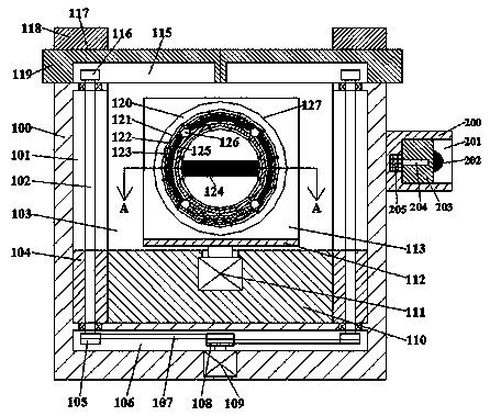
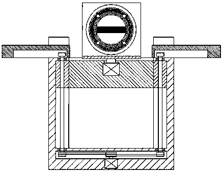
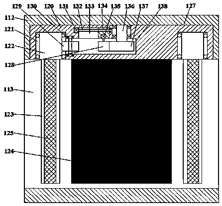
[0016] Such as figure 1 , figure 2 with image 3 As shown, a multifunctional low-power and high-power concentrating solar cell of the present invention includes a box body 100 and a storage groove 103 arranged in the box body 100 with an upward opening. The left and right inner walls of the storage groove 103 are communicated with each other. The first guide sliding groove 101 is provided with a first cavity 106 at the bottom of the receiving groove 103, a first guide slider 110 is slidably connected in the receiving groove 103, and the first guide sliding groove 101 is slidingly connected and connected There is a second guide slider 104. The end surface of the second guide slider 104 close to the first guide slider 110 is fixedly connected to the corresponding end surface. An extended lifting threaded rod 102. The bottom of the lifting threaded rod 102 extends into the first cavity 106 and is provided with a first pulley 105. The top of the lifting threaded rod 102 extends be...


PUM


Abstract

The present invention discloses a multi-functional low magnification and high magnification light-concentration solar cell. The solar cell comprises a box body and a containing slot arranged in the box body, wherein the opening of the containing slot is upward. The insides of the left inner wall and the right inner wall of the containing slot are interlinked, and the containing slot is provided with a first slide-guiding chute. The bottom of the containing slot is provided with a first cavity. The containing slot is slidably connected with a first slide-guiding block, wherein the containing slot is matched with the first slide-guiding block. The first slide-guiding chute is slidably connected with a second slide-guiding block, wherein the first slide-guiding chute is matched with the second slide-guiding block. The end face, near the first slide-guiding block, of the second slide-guiding block is fixedly connected with the corresponding end face of the first slide-guiding block. The second slide-guiding block is threadedly connected with a lifting threaded rod, wherein the lifting threaded rod extends up and down, and the second slide-guiding block is matched with lifting threadedrod. The bottom of the lifting threaded rod stretches into the first cavity, and the bottom of the lifting threaded rod is provided with a first belt wheel. The top of the lifting threaded rod stretches out of the top end face of the box body, and the top of the lifting threaded rod is provided with a second gear. The solar cell has the advantages of simple structure, stable regulation, good light-concentration effect, high energy conversion efficiency, stable magnification regulation and relatively-high practical performance.

Description

Technical field [0001] The invention relates to the technical field of new energy, in particular to a multifunctional low-power and high-power concentrating solar cell. Background technique [0002] With the development of science and technology and the progress of society, the country has been promoting the development of high technology. In the field of new energy technology, there has always been a relatively difficult technical problem. The current solar cells have a large laying area and the cost of solar panels. Higher, ordinary solar panels have poor light concentration and lower energy conversion rate. For solar panels that can adjust multiples, it is difficult to adjust the angle, resulting in limited light focusing effect. This device effectively solves this problem. Summary of the invention [0003] The technical problem to be solved by the present invention is to provide a multifunctional low-power and high-power concentrating solar cell, which can solve the above-ment...

Claims


Application Information

Patent Timeline
IPC IPC(8): H02S20/30H02S40/22
CPCH02S20/30H02S40/22Y02E10/52
Inventor 斯幼云
Owner 斯幼云
Why Eureka
Try Eureka