
Rotary trimming shears

A technology of disc shearing and edge trimming, which is applied in the direction of shearing machine equipment, shearing devices, and knives used in shearing machine devices, can solve the problems of inconvenient maintenance of edge trimming disc shears, and achieve easy maintenance and maintenance, The effect of ensuring the trimming accuracy

Active Publication Date: 2017-01-04
CERI TECH +1
View PDF7 Cites 0 Cited by
  • Summary
  • Abstract
  • Description
  • Claims
  • Application Information

AI Technical Summary

Problems solved by technology

[0012] In order to overcome the disadvantage of inconvenient maintenance of the existing trimming disc shears, the present invention provides a trimming disc shears to achieve the purpose of easy maintenance

Method used


Image

  • Rotary trimming shears
  • Rotary trimming shears
  • Rotary trimming shears

Examples


Embodiment Construction

[0036] It should be noted that, in the case of no conflict, the embodiments in the present application and the features in the embodiments can be combined with each other. The present invention will be described in detail below with reference to the accompanying drawings and examples.

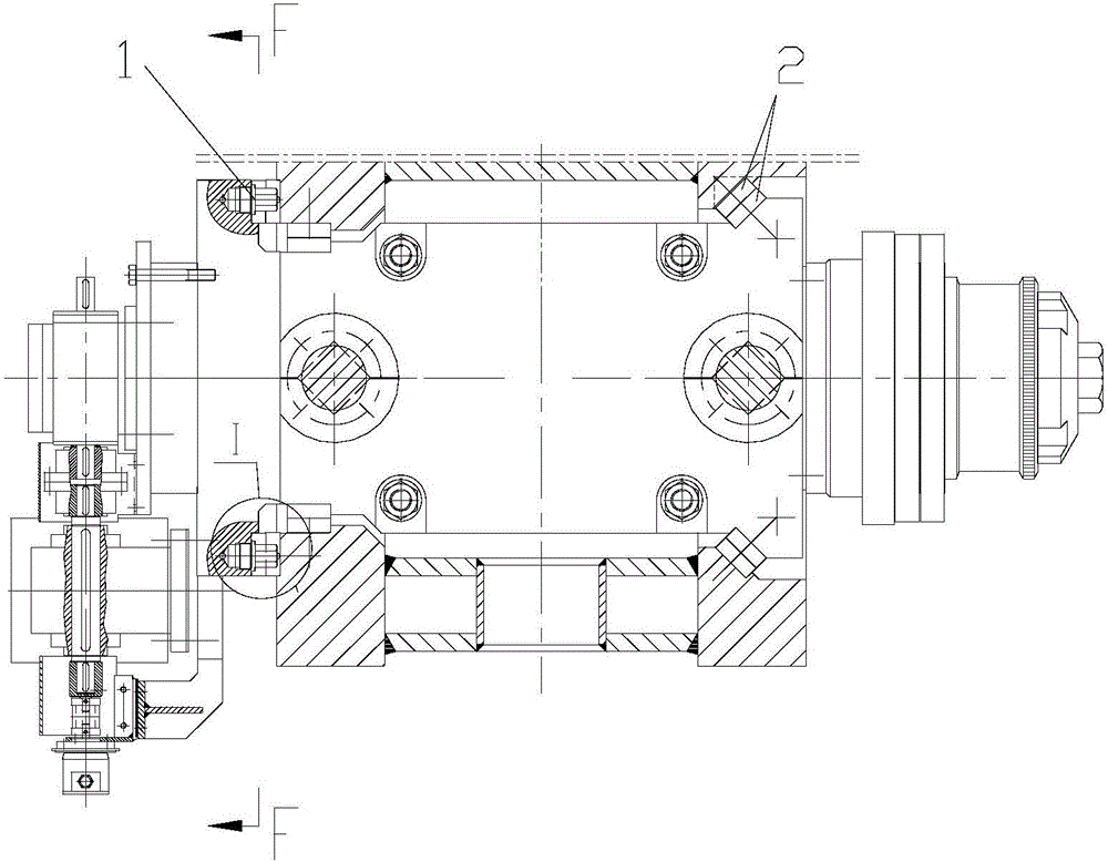
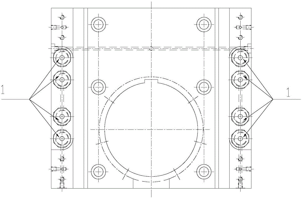
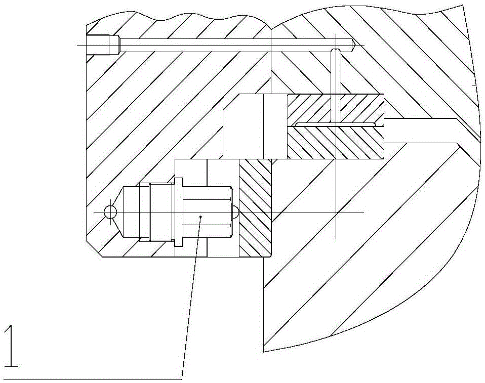
[0037] Such as Figure 4 to Figure 8 As shown, the embodiment of the present invention provides a kind of trimming disc shears, which includes a frame 10, a cutter shaft seat 20 arranged on the frame 10, a cutter head locking device 30 and a drive assembly 32 . A rotatable upper cutter shaft 71 is pierced in the cutter shaft seat 20 . The cutterhead locking device 30 includes a wedge groove 21 and a locking wedge shaft 31 . The wedge-shaped groove 21 is arranged on the outer peripheral wall of the knife shaft seat 20 (the knife shaft seat 20 is a cube structure). The locking cam shaft 31 is connected with the driving assembly 32, and the driving assembly 32 can drive the locking cam shaft 3...


PUM


Abstract

The invention provides rotary trimming shears. The rotary trimming shears comprise a rack as well as a cutter shaft seat, a cutter head locking device and a drive assembly which are arranged on the rack, wherein a rotatable upper cutter shaft penetrates the cutter shaft seat and is used for cooperating with a lower cutter shaft fixed on the rack to shear strips; the cutter head locking device comprises a wedge-shaped groove formed in the peripheral wall of the cutter shaft seat as well as a locking wedge shaft connected with the drive assembly, the drive assembly can drive the locking wedge shaft to move in the direction perpendicular to the axes of the cutter shafts, and the locking wedge shaft can cooperate with the wedge-shaped groove and limit radial displacement in the horizontal direction and axial displacement of the cutter shaft seat. The rotary trimming shears have the beneficial effects that radial displacement in the horizontal direction and axial displacement of the cutter shaft seat of the rotary trimming shears can be locked through cooperation of the wedge-shaped groove and the locking wedge shaft, play of the upper cutter shaft of the rotary trimming shears during strip shearing is avoided, and the contact ratio and the side clearance of the cutter head are stable and unchanged, so that the strip trimming precision is guaranteed and the requirement for quality of high-quality products is met.

Description

technical field [0001] The invention relates to the field of rolling process equipment, in particular to an edge trimming disc shear for cutting the edge of strip steel. Background technique [0002] The function of the trimming disc shear is to drive the upper and lower cutter shafts of the shearing machine through the strip steel or power, so that the disc-shaped cutter assembled on the cutter shaft rotates with the movement of the strip steel, and cuts the edge of the strip steel, so that the strip steel can obtain Excellent edge quality finally meets the requirements of the next rolling process and finished product quality. [0003] The principle of disc shearing strip steel is: the upper and lower cutter heads have a certain amount of overlap in the diameter direction (hereinafter referred to as coincidence degree), and the gap between the end faces of the two cutter heads is very small (hereinafter referred to as side clearance). When running into the cutting edge of ...

Claims


Application Information

Patent Timeline
IPC IPC(8): B23D19/04B23D35/00
CPCB23D19/04B23D35/004B23D35/007
Inventor 宋小兵丁殿恺
Owner CERI TECH
Learn More