
A Circular Cutting Drive System

A drive system, cycle-type technology, applied in the direction of photovoltaic power generation, sustainable manufacturing/processing, electrical components, etc., can solve the problems of high cost, multiple drive structures, complex control system, etc., achieve low cost of use, and ensure the effect of cutting edges , Guarantee the effect of trimming precision

Inactive Publication Date: 2017-12-08
无锡嘉友联智能装备有限公司
View PDF6 Cites 0 Cited by
  • Summary
  • Abstract
  • Description
  • Claims
  • Application Information

AI Technical Summary

Problems solved by technology

[0002] Solar panel trimming machine, the main function is that during the production process of solar panels, the overflow edge needs to be cut off after lamination. At present, multiple knives are generally used on the trimming machine to trim the four sides, and each tool needs to be individually Equipped with a drive system to move the tool, resulting in more drive structures, complex control systems, and higher costs

Method used


Image

  • A Circular Cutting Drive System

Examples


Embodiment Construction

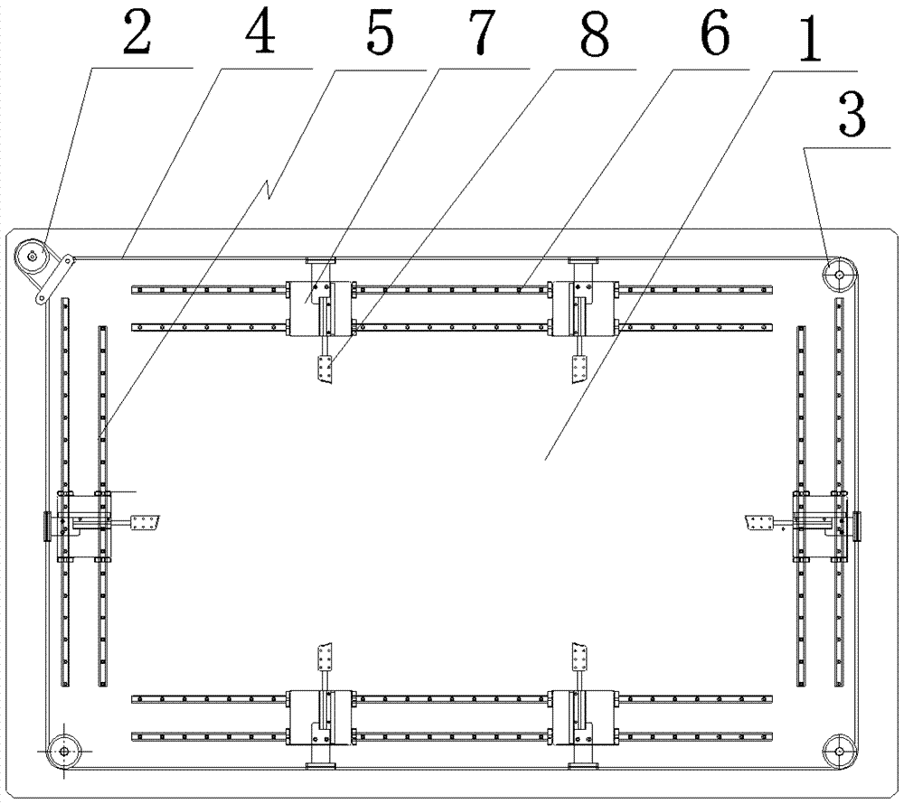
[0009] See figure 1 As shown, a circular chamfering drive system includes a mounting plate 1, a driving synchronous pulley 2 is installed on one corner of the mounting plate 1, a reversing synchronous pulley 3 is respectively installed on the other three corners, and a synchronous belt 4. After bypassing the driving synchronous pulley 2 and the reversing synchronous pulley 3 in sequence, it forms a rectangular shape. The inner side of the synchronous belt 4 is arranged on four guide rails 5, and each guide rail 5 is composed of two parallel linear guide rails 6 The four guide rails 5 form a rectangular shape corresponding to the synchronous belt 4, each guide rail 5 is equipped with a sliding seat 7, and each sliding seat 7 is fixedly connected to the synchronous belt 4, and the sliding seat 7 is equipped with a cutting Edge Knife8. Two sliding seats 7 are installed on the wire guide rail 5 corresponding to the long side of the rectangle.


PUM


Abstract

The invention relates to a technology field of edge chipping after solar energy assembly lamination, to be specific, relates to a circulating type edge chipping driving system. Four-edge chipping operation is realized under driving of a single motor, and therefore a structure is simple, and a cost is low. The edge chipping driving system comprises an installation plate, and one corner of the installation plate is provided with a driving synchronous pulley, and the other three corners are respectively provided with a commutating synchronous pulley. A synchronous belt is sequentially wound around the driving synchronous pulley and the commutating synchronous pulleys to form a rectangle. The inner side of the synchronous belt is provided with four guide rails, which are arranged in the shape of a rectangle corresponding to the rectangle shape formed by the synchronous belt. Each of the guide rails is provided with a slider, which is fixedly connected with the synchronous belt, and is provided with an edge chipping knife.

Description

technical field [0001] The invention relates to the technical field of edge trimming after lamination of solar modules, in particular to a circular edge trimming drive system. Background technique [0002] Solar panel trimming machine, the main function is that in the production process of solar panels, the overflow edge needs to be cut off after lamination. At present, multiple knives are generally used on the trimming machine to trim the four sides, and each tool needs to be individually Equipped with a driving system to move the tool, resulting in more driving structures, complicated control system and higher cost. Contents of the invention [0003] In order to solve the above problems, the present invention provides a circular edge trimming drive system, which can realize four-sided edge trimming operations through a single motor drive, with simple structure and low cost. [0004] The technical solution is as follows: a circular edge trimming drive system, characteriz...

Claims


Application Information

Patent Timeline
Patent Type & Authority Patents(China)
IPC IPC(8): H01L31/18
CPCH01L31/1876Y02E10/50Y02P70/50
Inventor 蒋洪斌
Owner 无锡嘉友联智能装备有限公司
Learn More