
Dehumidification device

A drying and dehumidifying, outlet-side technology, applied in substation/distribution device housing, substation/switchgear cooling/ventilation, substation/switch layout details, etc. technical inefficiency

Pending Publication Date: 2018-11-06
GUANGDONG POWER GRID CO LTD +1
View PDF5 Cites 5 Cited by
  • Summary
  • Abstract
  • Description
  • Claims
  • Application Information

AI Technical Summary

Problems solved by technology

[0006] The purpose of the present invention is to provide a dehumidification device to alleviate the defects of the anti-condensation and moisture-proof dead zone in the heating and dehumidification technology in the prior art, which cannot fully realize the moisture-proof and anti-condensation, and the condensation and dehumidification technology has low efficiency and water leakage. risk technical issues

Method used


Image

  • Dehumidification device
  • Dehumidification device
  • Dehumidification device

Examples


Embodiment Construction

[0043] The technical solutions of the present invention will be clearly and completely described below in conjunction with the accompanying drawings. Apparently, the described embodiments are some of the embodiments of the present invention, but not all of them. Based on the embodiments of the present invention, all other embodiments obtained by persons of ordinary skill in the art without making creative efforts belong to the protection scope of the present invention.

[0044] In the description of the present invention, it should be noted that if the terms "center", "upper", "lower", "left", "right", "vertical", "horizontal", "inner", "outer" appear ", etc., the indicated orientation or positional relationship is based on the orientation or positional relationship shown in the drawings, which is only for the convenience of describing the present invention and simplifying the description, rather than indicating or implying that the referred device or element must have a specif...


PUM


Abstract

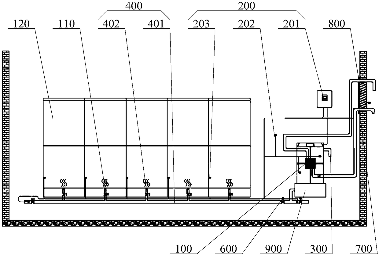
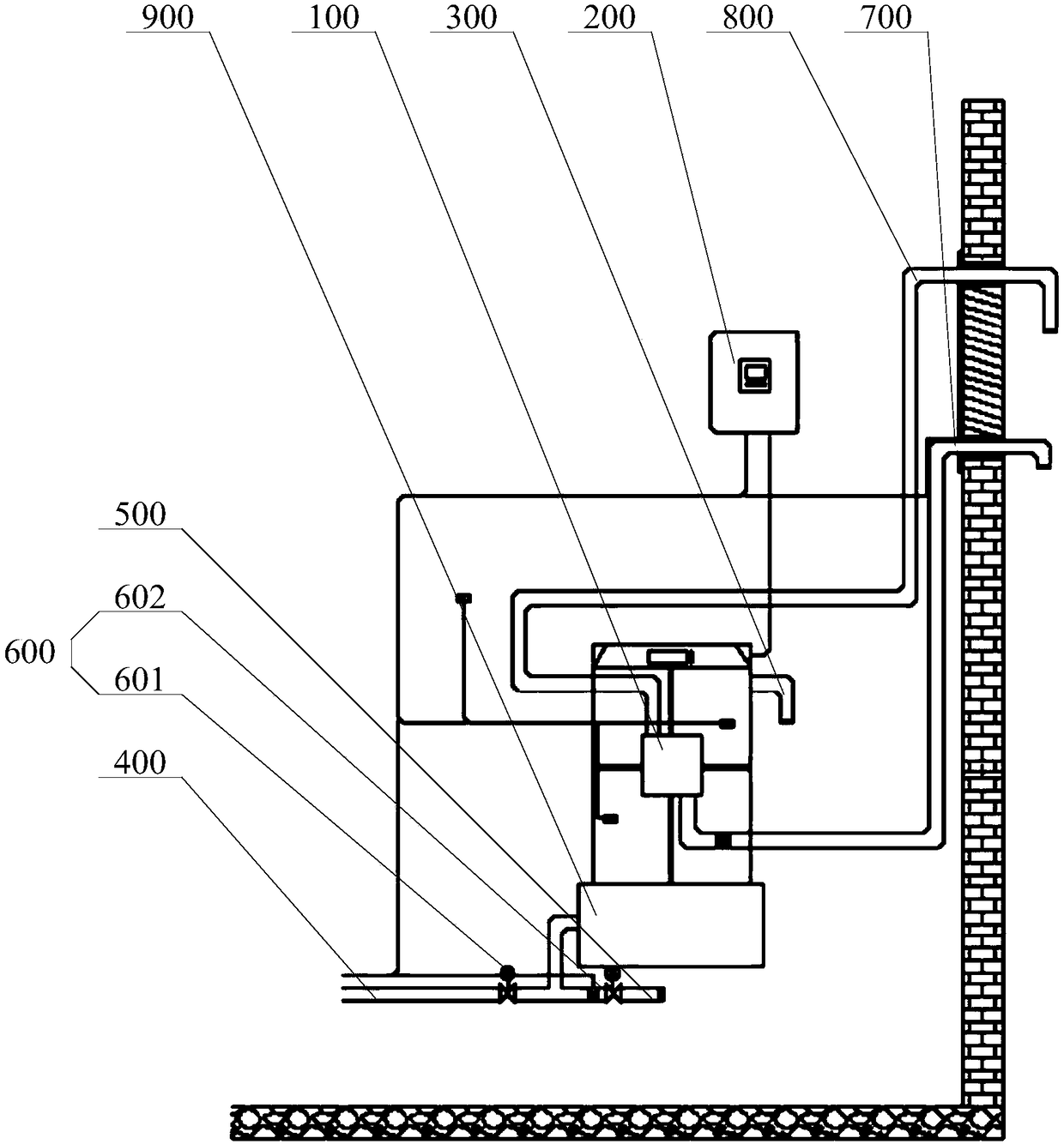
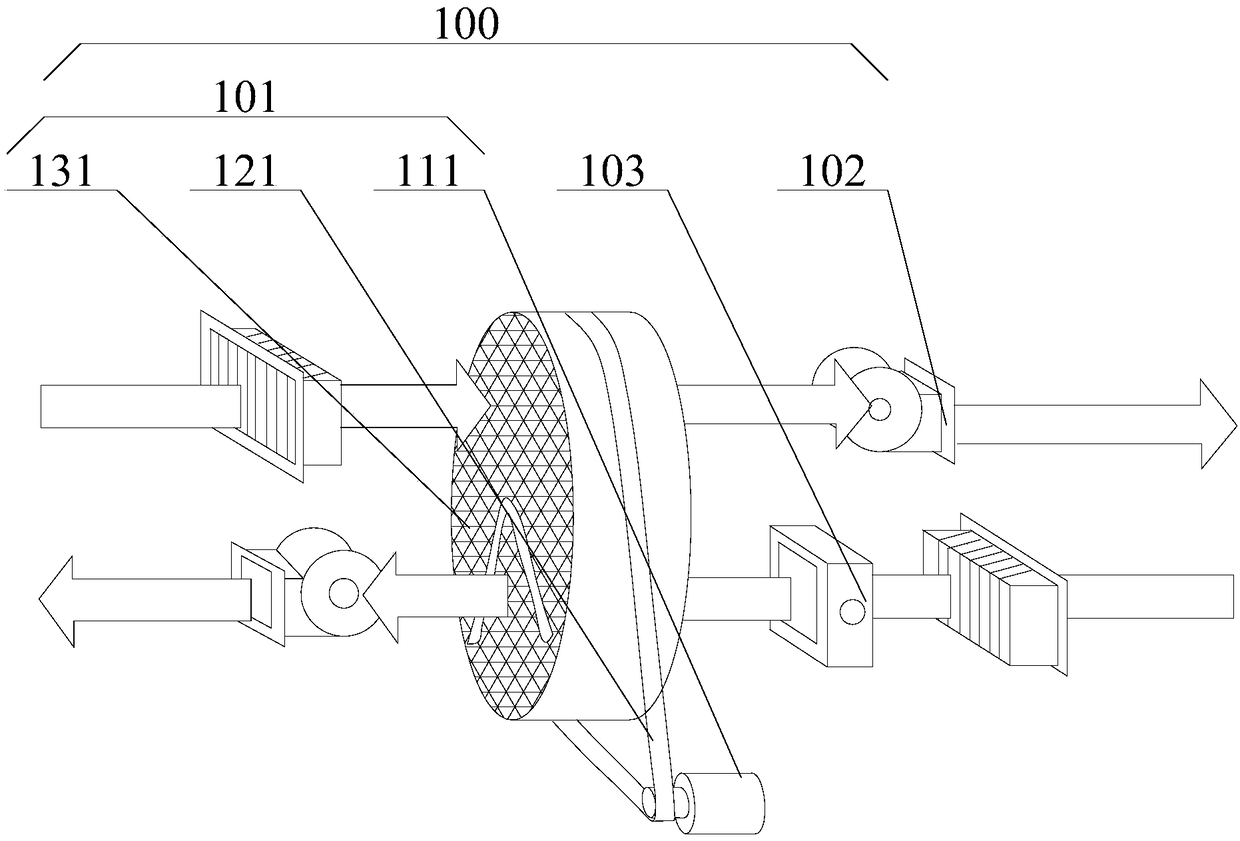
The invention provides a dehumidification device, and relates to the technical field of electrical equipment. The dehumidification device comprises a drying and dehumidifying mechanism, a monitoring system, a circulating air inlet part, a first outlet end, a second outlet end and a regulating valve, wherein the air enters from the circulating air inlet part, after the moisture is absorbed by the drying and dehumidifying mechanism, the air is changed into dry air, the dry gas coming out of the drying and dehumidifying mechanism is controlled by the regulating valve and is supplied to power equipment or an indoor room, and the moisture of the power equipment or the indoor air is absorbed and becomes dry; the operation of an air source and an air distribution system is monitored through the monitoring system, and a condensation point temperature and a given control value can be calculated according to temperature and humidity acquisition data of the power equipment, so that a purpose of adjusting the temperature and the humidity in the power equipment is achieved, and the temperature and humidity are far away from a condensation point; a defect that the moisture prevention and the condensation prevention cannot be completely achieved in the prior art and the technical problem of low efficiency are alleviated; and the technical effects of fast dehumidification, high efficiency, great dehumidification capability and high safety are achieved.

Description

technical field [0001] The invention relates to the technical field of electric equipment, in particular to a dehumidification device. Background technique [0002] 12kV high-voltage switchgear is a kind of power equipment widely used in urban power supply and distribution systems. Changes in the temperature and humidity of its internal environment, as well as the completeness of airtightness, will affect its normal operation. When the switchgear is overhauled, it will inevitably cause external humid air to enter the inside of the cabinet, which will easily cause damp and dew inside the switchgear. If the switchgear is in such an environment for a long time state, the inside of the cabinet is prone to various vicious short-circuit faults, including single-phase short-circuit, two-phase short-circuit, and even three-phase short-circuit. In addition, long-term moisture condensation will lead to the gradual reduction of the insulation performance inside the cabinet, resulting ...

Claims


Application Information

Patent Timeline
IPC IPC(8): H02B1/56H02B1/28
CPCH02B1/28H02B1/565
Inventor 杨芳唐小亮范平涛潘岐泽
Owner GUANGDONG POWER GRID CO LTD
Learn More