
Printing system and method for automatically generating printing bleeding position and cutting line

A technology of automatic generation and printing system, applied in the field of printing industry, can solve the problems of low bleeding efficiency and low quality, and achieve the effect of improving matching effect, improving quality and improving printing work efficiency.

Active Publication Date: 2018-11-06
广州多普网络科技有限公司 +1
View PDF4 Cites 4 Cited by
  • Summary
  • Abstract
  • Description
  • Claims
  • Application Information

AI Technical Summary

Benefits of technology

This technology helps reduce labor costs by automating the process of producing colored prints without requiring human operators or equipment. It also allows automatic analysis of pattern, colors, etc., allowing for faster identification of any issues during printing processes while maintaining high-quality results.

Problems solved by technology

This patents describes how manual methods like handheld tools can cause unwanted waste when removing certain areas on screens from their final products. Additionally, there has been an increase demand over recent years towards higher levels of automation and precision in manufacturing processes without sacrificially affecting visual appeal. These issues have led researchers around the world to study ways to improve upon existing techniques while reducing labor costs associated with producing these types of materials more efficiently.

Method used


Image

  • Printing system and method for automatically generating printing bleeding position and cutting line

Examples


Embodiment Construction

[0053] The preferred embodiments of the present invention will be described below in conjunction with the accompanying drawings. It should be understood that the preferred embodiments described here are only used to illustrate and explain the present invention, and are not intended to limit the present invention.

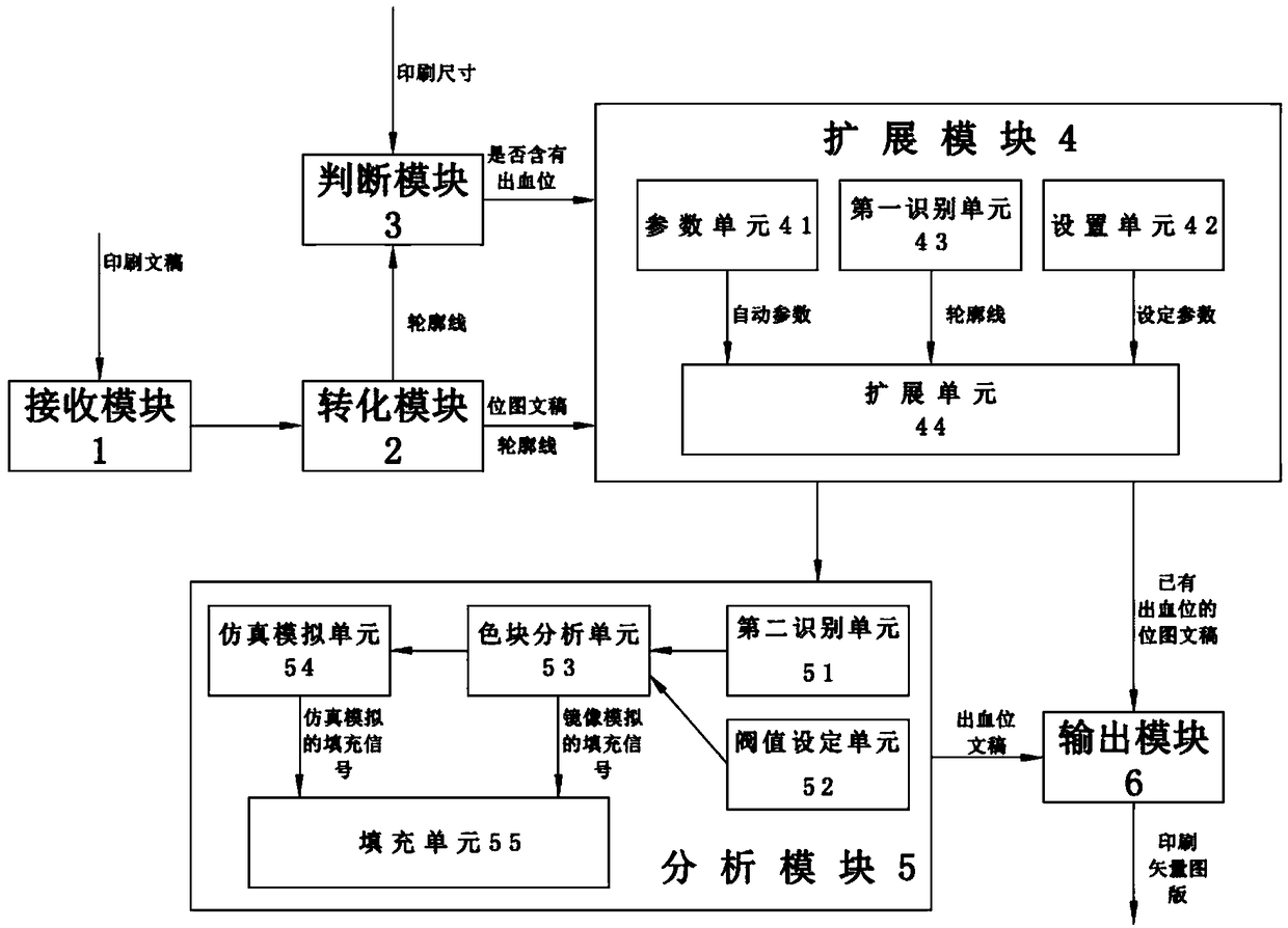
[0054] A method for automatically generating printing bleeds and cutting lines according to the present invention comprises the following steps:

[0055] S1. Obtain a printed document.

[0056] S2. Convert the printed manuscript of the above S1 into a bitmap manuscript, and generate the outline of the bitmap manuscript:

[0057] S21. Identify and classify the pixel units of the printed document, collect the same and continuous pixel units, and divide multiple pixel groups on the bitmap document;

[0058] S22. Convert the pixel group into a color block bitmap, and multiple color block bitmaps form a bitmap document; through the color contrast between the bitmap docu...


PUM


Abstract

The invention discloses a method for automatically generating a printing bleeding position and a cutting line, which comprises the following steps: S1, obtaining a printed document; S2, converting theprinted document into a bitmap document, and generating a contour line of the bitmap document; S3, judging whether the bitmap document contains a bleeding position according to the set printing size;if the bitmap document contains the bleeding position, enabling the contour line to be retracted to generate the cutting line according to the set expansion parameters; if the bitmap document does not contain the bleeding position, executing step S4; S4, enlarging the contour line to generate a bleeding area according to the set expansion parameters, and filling the bleeding area with a color and/or a pattern to generate a bleeding position document, wherein the contour line constitutes the cutting line of the bleeding position document; and S5, converting the bitmap document containing the cutting line in S3 or the bleeding bitmap document in S4 into a printed vector plate. The bleeding position is automatically generated to improve the quality of a printed matter.

Description


Claims


Application Information

Patent Timeline
Owner 广州多普网络科技有限公司
Learn More