A swing ceiling fan for dormitory based on power adjustment format
A width and dormitory technology, applied in the field of living utensils, can solve the problems that the side beds cannot be blown to the wind, the fan has insufficient wind width, etc., and achieve the effect of stable support and increased blowing area
- Summary
- Abstract
- Description
- Claims
- Application Information
AI Technical Summary
Problems solved by technology
Method used
Image
Examples
Embodiment 1
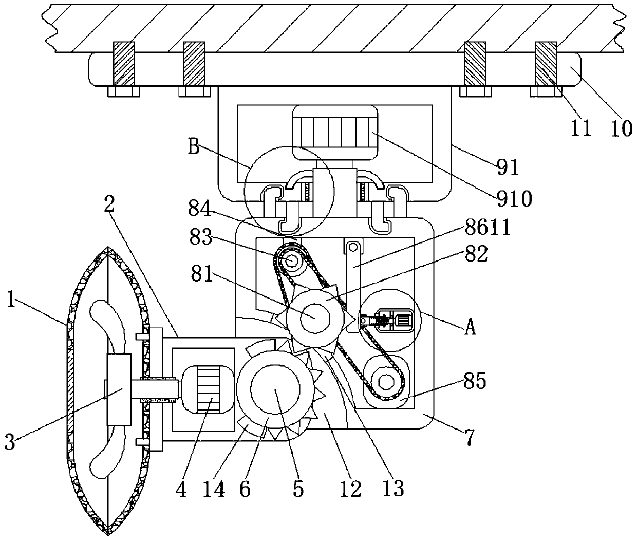
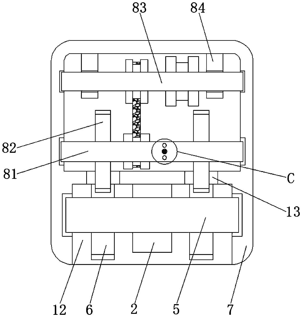
[0033] Such as Figure 1-5As shown, a dormitory swing-head ceiling fan based on power adjustment format includes a fan cover 1, a transmission column 2 is arranged on one side of the fan cover 1, fan blades 3 are provided in the inner cavity of the fan cover 1, and the inside of the transmission column 2 The first motor 4 is fixedly connected, the end of the transmission column 2 away from the fan cover 1 is fixedly connected with the transmission shaft 5, the two ends of the transmission shaft 5 are symmetrically fixedly connected with the first gear 6, and one end of the transmission column 2 is provided with a rotation column 7, The inner cavity of the rotating column 7 is provided with a drive mechanism 8, the top of the rotating column 7 is provided with an amplifying mechanism 9, the top of the amplifying mechanism 9 is provided with a fixed plate 10, and both sides of the fixed plate 10 bottom are symmetrically provided with bolts 11, and the rotating column 7 The botto...
Embodiment 2
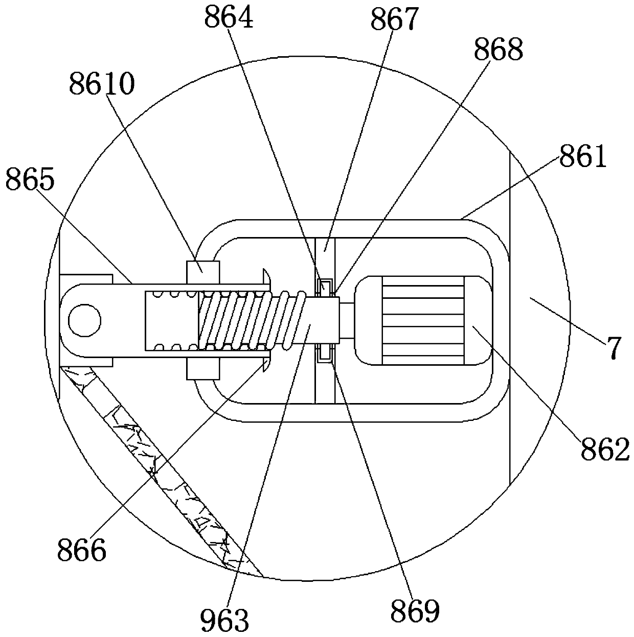
[0035] On the basis of Embodiment 1, the fixing mechanism 86 includes a pressure-bearing box 861, and a third motor 862 is fixedly connected to the middle of one side of the inner wall of the pressure-bearing box 861. shaft, the end of the output shaft of the third motor 862 is fixedly connected with a threaded rod 863, the top and bottom of the threaded rod 863 are symmetrically fixedly connected with a slider 864 on the side close to the third motor 862, and the other end of the threaded rod 863 is provided with a threaded sleeve 865 The top and bottom of the threaded sleeve 865 are symmetrically fixedly connected with a block 866 on one side close to the threaded rod 863, and a threaded groove is opened in the middle of one side of the threaded sleeve 865.
Embodiment 3
[0037] On the basis of Embodiments 1 and 2, the middle part of the inner cavity of the pressure box 861 is fixedly connected to the limiting plate 867, the middle part of the limiting plate 867 is provided with a through hole 868 passing through it, and the four sides of the inner wall of the through hole 868 are provided with annular The chute 869, the center of the other side of the pressure box 861 is provided with a first opening, the first opening is fixedly connected with a limit block 8610, the other end of the threaded rod 863 is rotatably connected with a moving rod 8611, and the moving rod 8611 is away from the threaded rod 863 A fixed block 8612 is fixedly connected to the bottom of one side.
PUM
 Abstract
Description
Claims
Application Information
 - R&D
- Intellectual Property
- Life Sciences
- Materials
- Tech Scout
- Unparalleled Data Quality
- Higher Quality Content
- 60% Fewer Hallucinations
Browse by: Latest US Patents, China's latest patents, Technical Efficacy Thesaurus, Application Domain, Technology Topic, Popular Technical Reports.
© 2025 PatSnap. All rights reserved.Legal|Privacy policy|Modern Slavery Act Transparency Statement|Sitemap|About US| Contact US: help@patsnap.com


