Rotary electric conduction device and electroplating device

A technology of conductive device and conductive ring, applied in the direction of current conduction device, electrode, electrolysis process, etc., can solve the problems of wear and the unusable rotating conductive structure, and achieve the purpose of increasing the conductive performance, ensuring the stability of the electrical connection and reducing the degree of wear and tear. Effect

Pending Publication Date: 2018-11-06
NANTONG HUIFENG ELECTRONICS TECH
View PDF4 Cites 2 Cited by
  • Summary
  • Abstract
  • Description
  • Claims
  • Application Information

AI Technical Summary

Problems solved by technology

However, this rotating conductive structure is only suitable for electrical devices with a small current. When it is used on a device with a large current such as electroplating, due to the heat generated by excessive current and serious wear, the rotating conductive structure cannot be used.

Method used


Image

  • Rotary electric conduction device and electroplating device
  • Rotary electric conduction device and electroplating device
  • Rotary electric conduction device and electroplating device

Examples


Embodiment 1

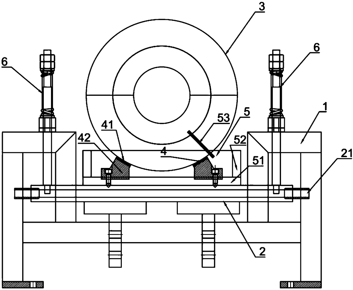
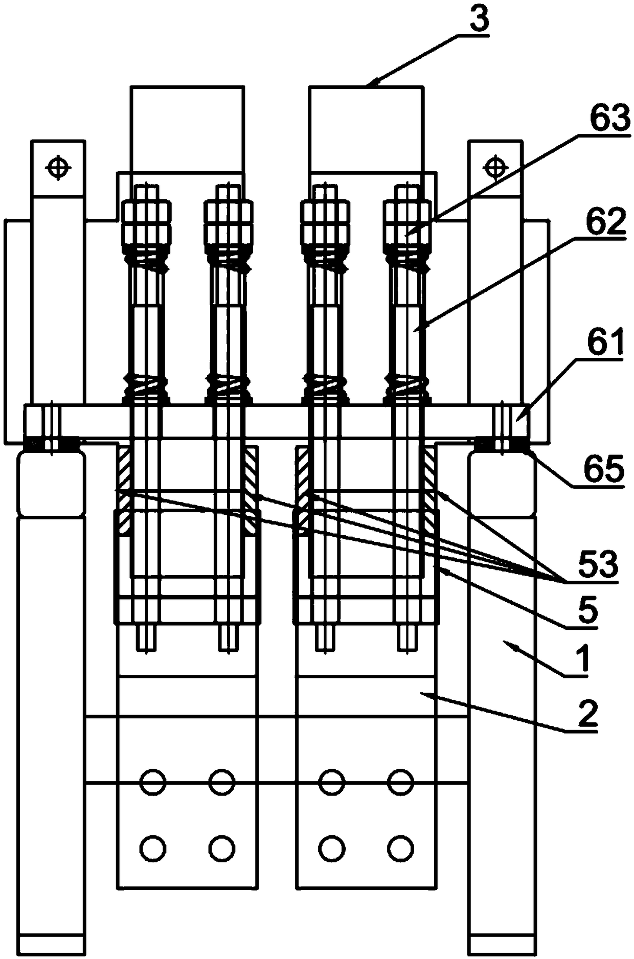
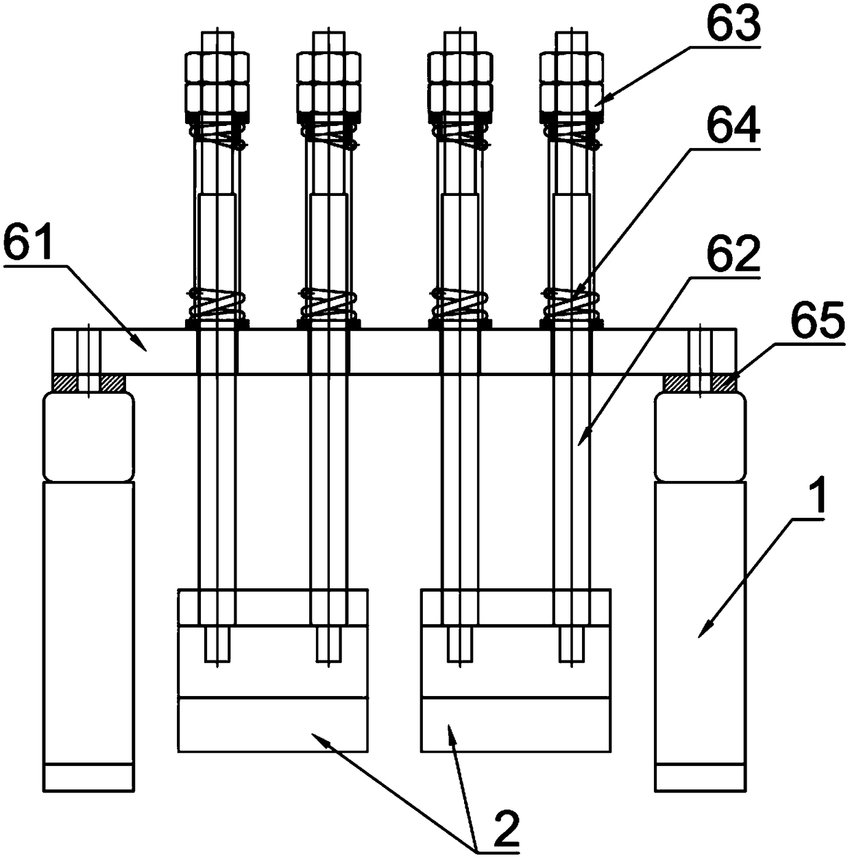
[0050] This embodiment provides a rotating conductive device, the structure of which is as follows figure 1 As shown, it includes a rotating shaft driven by a driving device (not shown in the figure). A conductive ring 3 is sleeved on the rotating shaft, and the conductive ring 3 rotates together with the rotating shaft. The bottom of the conductive ring 3 is provided with a mounting seat 2, and the electrode assembly 4 is installed on the mounting seat 2 and is electrically connected to the surface of the conductive ring 3; the mounting seat 2 is also provided with a conductive oil pool 5, which contains conductive oil, and the electrodes The contact point between the assembly 4 and the conductive ring 3 is immersed in conductive oil for lubricating the contact point between the conductive ring 3 and the electrode assembly 4 . The conductive oil immerses the contact point between the electrode assembly 4 and the conductive ring 3 below its liquid level to reduce the friction...

Embodiment 2

[0069] This embodiment provides an electroplating device, including the rotating conductive device in Embodiment 1, the rotating conductive device is connected between the power supply device and the material to be electroplated, and is used to transmit power to the material to be electroplated. Specifically, the rotating conductive device connects the cathode of the high-power rectifier with the drum wound by the electroplated steel wire rod, and is used for high-efficiency production of electroplated copper-clad steel.


PUM


Abstract

The invention provides a rotary electric conduction device. The rotary electric conduction device comprises a rotating shaft, an electric conduction ring and an electrode assembly. The electric conduction ring is arranged on the rotating shaft in a sleeving manner and rotates jointly along with the rotating shaft, the electrode assembly is arranged on a mounting base and is in electric conductionconnection with the surface of the electric conduction ring, an electric conduction oil pond is arranged on the mounting base, electric conduction oil is contained in the electric conduction oil pond,the contact point of the electrode assembly and the electric conduction ring is immersed below the electric conduction oil liquid face, friction force between the electrode assembly and the electricconduction ring is reduced, the wear degree of the electrode assembly and the electric conduction ring is reduced, and the electric conduction property is improved. The invention further provides an electroplating device. The electroplating device comprise the rotary electric conduction device and used for transmitting power to a material to be electroplated.

Description

technical field [0001] The invention relates to the technical field of electroplating devices, in particular to a rotating conductive device for rotating transmission of large current. Background technique [0002] Conductive rings can be used in any electromechanical system that requires continuous rotation while transmitting power and signals from a fixed position to a rotating position. Slip rings can improve system performance, simplify system structure, and prevent wires from being twisted during rotation. Most of the existing conductive rings use sliding friction contact for current transmission. After a certain number of rotations, the degree of wear between the contact points continues to increase, and the wear is getting worse. On the one hand, it affects the contact resistance of the current signal. On the other hand, the contact parts are more likely to wear through sliding contact, which in turn affects the service life. [0003] There is an existing conductive...

Claims


Application Information

Patent Timeline
Patent Type & Authority Applications(China)
IPC IPC(8): C25D17/00C25D17/12C25D5/06
CPCC25D5/06C25D17/007C25D17/12
Inventor 石明华宋小波陈健蔡成俊
Owner NANTONG HUIFENG ELECTRONICS TECH
Why Eureka
Try Eureka