Medical spine correction chair
A medical and spinal technology, applied in medical science, physical therapy, massage auxiliary supplies, etc., can solve problems such as spinal injuries and harm to health, and achieve the effect of reducing workload
- Summary
- Abstract
- Description
- Claims
- Application Information
AI Technical Summary
Problems solved by technology
Method used
Image

Examples
Embodiment 1
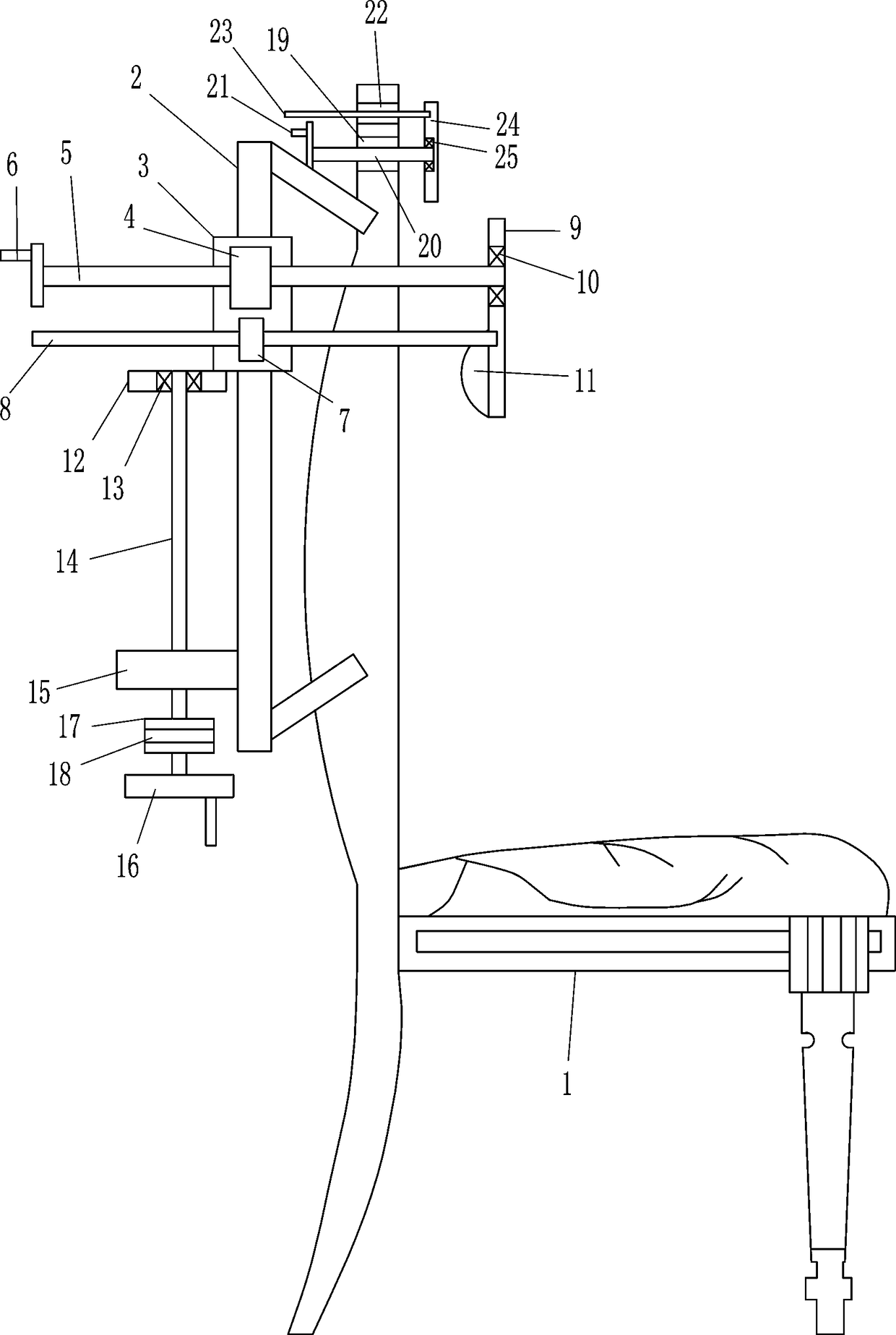
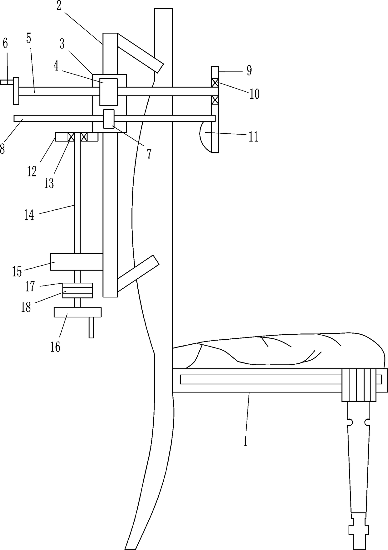
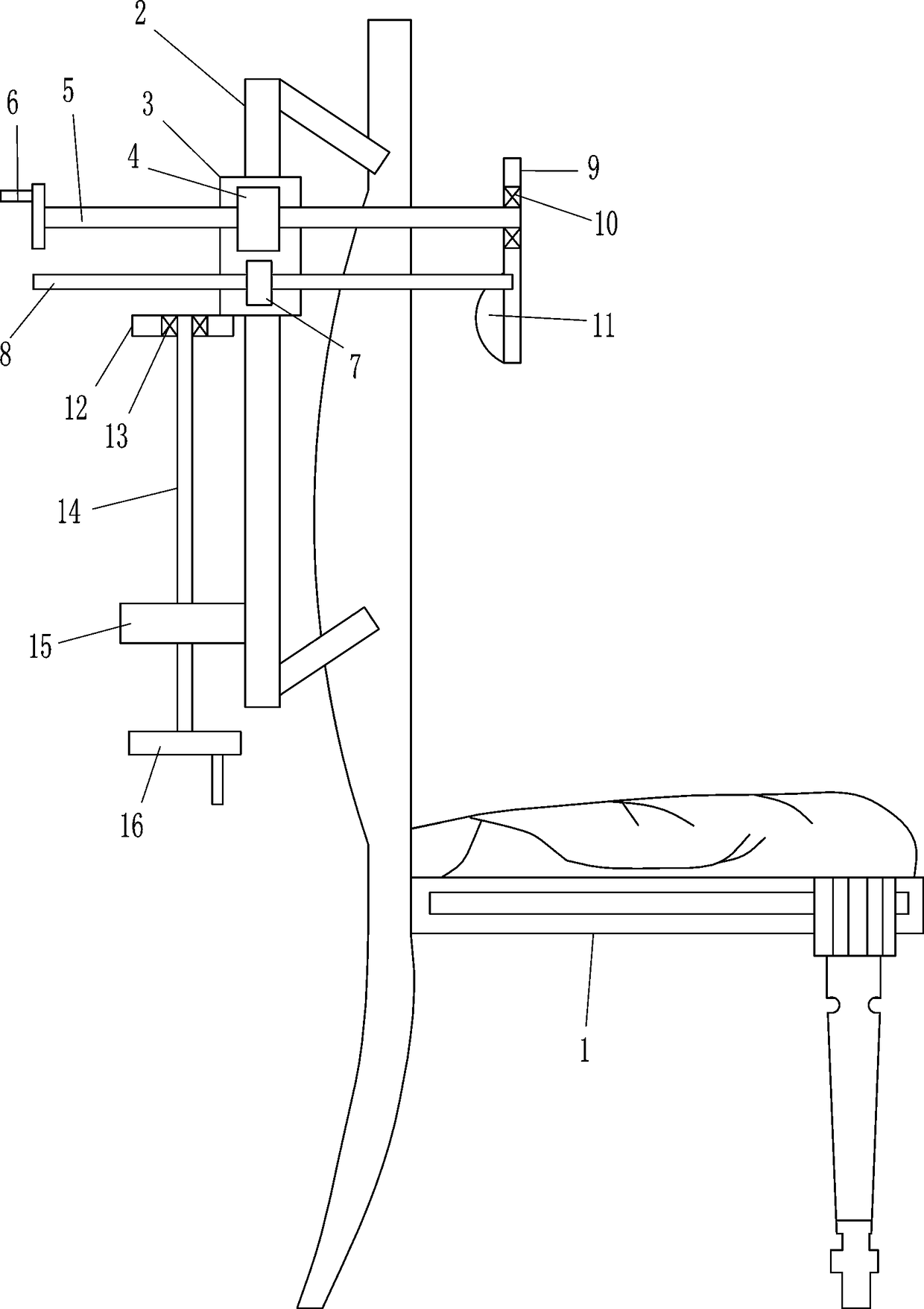
[0026] A chiropractic chair for medical use, such as Figure 1-6 As shown, it includes treatment chair 1, guide rail 2, first guide sleeve 3, first nut 4, first threaded rod 5, first handle 6, second guide sleeve 7, guide rod 8, first pressure plate 9, first Bearing seat 10, sponge 11, fixed block 12, second bearing seat 13, second threaded rod 14, second nut 15 and second handle 16, guide rail 2 is provided on the upper left side of treatment chair 1, and slide type on guide rail 2 A first guide sleeve 3 is provided, and first nuts 4 are arranged on the front and rear sides of the first guide sleeve 3. The first nuts 4 on the front and rear sides are all connected with first threaded rods 5 through threaded connections. The first threaded rods 5 on the side pass through the first nuts 4 on the front and rear sides respectively, the left ends of the first threaded rods 5 on the front and rear sides are provided with first handles 6, and the lower parts of the front and rear si...
Embodiment 2
[0028] A chiropractic chair for medical use, such as Figure 1-6 As shown, it includes treatment chair 1, guide rail 2, first guide sleeve 3, first nut 4, first threaded rod 5, first handle 6, second guide sleeve 7, guide rod 8, first pressure plate 9, first Bearing seat 10, sponge 11, fixed block 12, second bearing seat 13, second threaded rod 14, second nut 15 and second handle 16, guide rail 2 is provided on the upper left side of treatment chair 1, and slide type on guide rail 2 A first guide sleeve 3 is provided, and first nuts 4 are arranged on the front and rear sides of the first guide sleeve 3. The first nuts 4 on the front and rear sides are all connected with first threaded rods 5 through threaded connections. The first threaded rods 5 on the side pass through the first nuts 4 on the front and rear sides respectively, the left ends of the first threaded rods 5 on the front and rear sides are provided with first handles 6, and the lower parts of the front and rear si...
Embodiment 3
[0031] A chiropractic chair for medical use, such as Figure 1-6 As shown, it includes treatment chair 1, guide rail 2, first guide sleeve 3, first nut 4, first threaded rod 5, first handle 6, second guide sleeve 7, guide rod 8, first pressure plate 9, first Bearing seat 10, sponge 11, fixed block 12, second bearing seat 13, second threaded rod 14, second nut 15 and second handle 16, guide rail 2 is provided on the upper left side of treatment chair 1, and slide type on guide rail 2 A first guide sleeve 3 is provided, and first nuts 4 are arranged on the front and rear sides of the first guide sleeve 3. The first nuts 4 on the front and rear sides are all connected with first threaded rods 5 through threaded connections. The first threaded rods 5 on the side pass through the first nuts 4 on the front and rear sides respectively, the left ends of the first threaded rods 5 on the front and rear sides are provided with first handles 6, and the lower parts of the front and rear si...
PUM
 Abstract
Description
Claims
Application Information
 - R&D
- Intellectual Property
- Life Sciences
- Materials
- Tech Scout
- Unparalleled Data Quality
- Higher Quality Content
- 60% Fewer Hallucinations
Browse by: Latest US Patents, China's latest patents, Technical Efficacy Thesaurus, Application Domain, Technology Topic, Popular Technical Reports.
© 2025 PatSnap. All rights reserved.Legal|Privacy policy|Modern Slavery Act Transparency Statement|Sitemap|About US| Contact US: help@patsnap.com