An automatic power cable laying equipment

A power cable, automatic technology, applied in the direction of cable laying equipment, etc., can solve the problems of simultaneous cable release, shaking, and cables entangled with each other, and achieve the effect of firm support

Active Publication Date: 2020-05-05
扬州市工二电力机具有限公司
View PDF6 Cites 0 Cited by
  • Summary
  • Abstract
  • Description
  • Claims
  • Application Information

AI Technical Summary

Problems solved by technology

[0004] In order to solve the above problems, the present invention provides an automatic laying equipment for power cables, which can solve the problem that the existing cable racks shake when the existing cable racks are used for cable laying, and the cables in two directions cannot be adjusted. Simultaneous payout, cables will be entangled with each other when the cables are paid out, the cables will rub against the ground of the cable well when the cables are conducting, the cables cannot be guided at a certain angle, and the guiding angle of the cables in the cable wells cannot be adjusted. It has the function of firmly supporting the cable pay-off frame and conducting adjustable angles for cables in different pay-off directions. The pay-off rack will not shake during pay-off, and it can pay off cables in two directions at the same time. The cables will not be entangled with each other when the cables are laid out, the cables will not rub against the ground of the cable well when the cables are conducting, the cables can be guided at a certain angle, and the guiding angle of the cables in the cable well can be adjusted, etc.

Method used


Image

  • An automatic power cable laying equipment
  • An automatic power cable laying equipment
  • An automatic power cable laying equipment

Examples


Embodiment Construction

[0029] In order to make the technical means, creative features, goals and effects achieved by the present invention easy to understand, the present invention will be further described below in conjunction with specific illustrations. It should be noted that, in the case of no conflict, the embodiments in the present application and the features in the embodiments can be combined with each other.

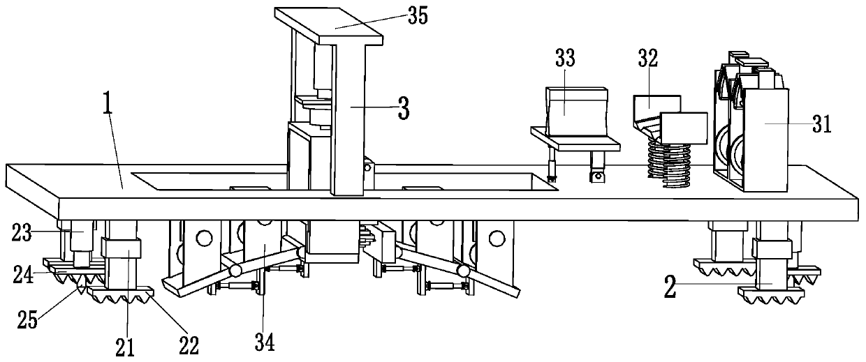
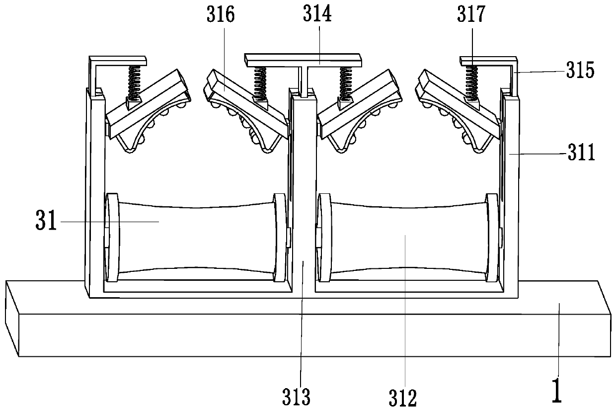
[0030] Such as Figure 1 to Figure 6 As shown, a power cable automatic laying equipment includes a support plate 1, a support device 2 and a wire release device 3, the left end of the support plate 1 is provided with a square groove, and the support device 2 is installed on the bottom of the support plate 1 On, the top of support plate 1 is installed with pay-off device 3.

[0031] The support device 2 includes a support telescopic column 21, a telescopic clamp 22, a support push rod 23, a support clamp 24 and a support insert 25, and the support telescopic column 21 is symmetricall...


PUM


Abstract

The invention relates to an automatic electric cable laying device, comprising a support plate, a support device and an unreeling device, wherein a square groove is arranged in the left side of the support plate, the support device is installed on the bottom of the support plate, and the unreeling device is installed on the top of the support plate; the support device comprises a support telescopic post, a telescopic clamping plate, a support push rod, a support clamping plate and a support plug post; the unreeling device comprises a limiting mechanism, a cable transmitting mechanism, a separating mechanism, a guiding mechanism and a guide regulating mechanism. The invention can solve problems that, in an existing cable bracket, an unreeling bracket may wobble when a cable is unreeled, cables in two unreeling directions cannot be unreeled at the same time, cables may be twisted with each other when unreeled, cables may have friction against the ground of a cable pit when transmitted, acable cannot be guided in a certain angle, and the guide angle of a cable in a cable pit cannot be adjusted, and so on.

Description

technical field [0001] The invention relates to the technical field of electric power construction, in particular to an automatic laying equipment for power cables. Background technique [0002] For the beauty of the city, bid farewell to the era of utility poles on the road. Now a large number of cables are conducted through underground cable wells. With the increasing number of underground cable wells, the workload of cable release is also increasing, especially Large cables are especially heavy. [0003] Now the cable is generally paid out by manually placing a pulley or a simple pay-off frame outside the cable well to pay off the cable, which will cause the cable to be scratched by the cable well or the cable will damage the cable well, the edge of the well cover and the waterproof layer, especially if you put more than one The problem is particularly serious when using cables. The specific problems existing when manually paying off cables are as follows. Unsmooth, it ...

Claims


Application Information

Patent Timeline
Patent Type & Authority Patents(China)
IPC IPC(8): H02G1/06
CPCH02G1/06
Inventor 徐盼盼
Owner 扬州市工二电力机具有限公司
Why Eureka
Try Eureka