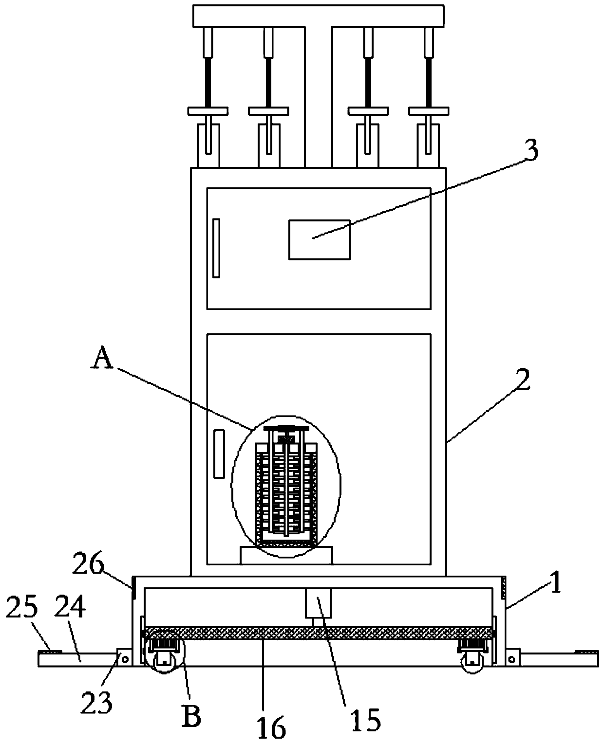
A cable refueling machine capable of uniform refueling

A fuel dispenser, a uniform technology, applied in cable/conductor manufacturing, circuits, electrical components, etc., can solve problems such as affecting production efficiency and quality, poor device placement performance, affecting the normal use of fuel dispensers, etc., to achieve cost savings, increase The effect of stirring efficiency

Active Publication Date: 2020-04-10
ANHUI CHUNHUI INSTR CABLE GROUP
View PDF6 Cites 0 Cited by
  • Summary
  • Abstract
  • Description
  • Claims
  • Application Information

AI Technical Summary

Problems solved by technology

[0004] The purpose of the present invention is to solve the problem that in the prior art, when large-scale oiling work is required, it is easy to cause the viscosity of the oil to be unable to be stirred in place in time, which affects the production efficiency and quality, and the stable placement performance of the device is poor. It is easy to change the displacement of the device when it is subjected to external collisions, which will affect the normal use of the fuel dispenser and cause damage to the fuel dispenser. A cable fuel dispenser that can refuel evenly is proposed.

Method used


Image

  • A cable refueling machine capable of uniform refueling
  • A cable refueling machine capable of uniform refueling
  • A cable refueling machine capable of uniform refueling

Examples


Embodiment Construction

[0022] The following will clearly and completely describe the technical solutions in the embodiments of the present invention with reference to the accompanying drawings in the embodiments of the present invention. Obviously, the described embodiments are only some, not all, embodiments of the present invention.

[0023] In describing the present invention, it should be understood that the terms "upper", "lower", "front", "rear", "left", "right", "top", "bottom", "inner", " The orientation or positional relationship indicated by "outside", etc. is based on the orientation or positional relationship shown in the drawings, and is only for the convenience of describing the present invention and simplifying the description, rather than indicating or implying that the referred device or element must have a specific orientation, so as to Specific orientation configurations and operations, therefore, are not to be construed as limitations on the invention.

[0024] refer to Figure ...


PUM


Abstract

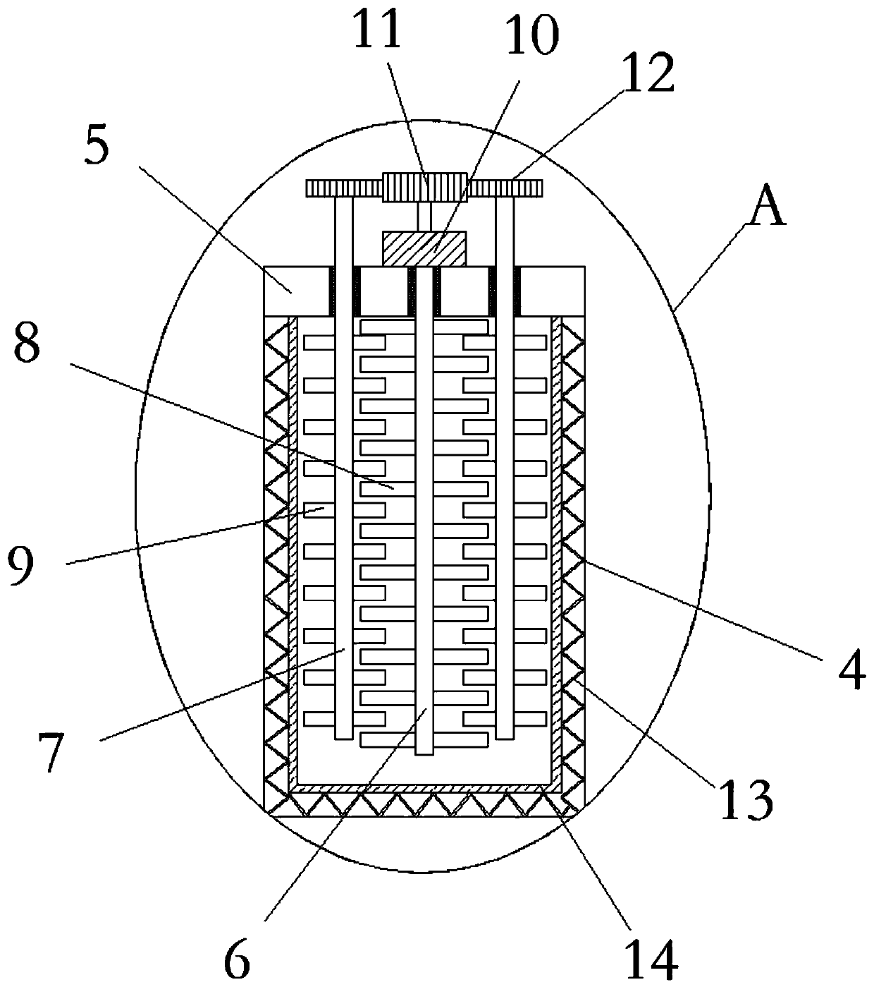
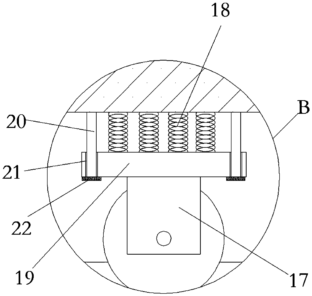
The invention discloses a cable oiling machine capable of oiling uniformly. The cable oiling machine comprises a base, a support which is positioned at the upper end of the base and is fixedly connected with the base and a pneumatic oil pump and a stirring mechanism which are positioned inside the support, wherein the base is of a hollow structure, and an opening is formed in the bottom of the base; a telescopic cylinder is fixedly arranged on the inner wall of the top of the base; a piston rod at the lower end of the telescopic cylinder is fixedly connected with a lifting plate; the four corners of the lower end of the lifting plate are fixedly connected with universal wheels through buffer mechanisms respectively; and stable mechanisms are fixedly arranged on the side wall of the periphery, close to the bottom, of the base respectively. According to the cable oiling machine, oil can quickly reach required viscosity, so that the production of cable oiling can be carried out continuously, and the stable placement of the oiling machine is increased.

Description

technical field [0001] The invention relates to the technical field of cable oiling machines, in particular to a cable oiling machine capable of uniform oiling. Background technique [0002] In the production process of the cable, the adhesion of the cable is an important indicator of the performance of the cable. Whether it is between the conductor and the insulating layer, or between the cable core and the outer sheath, there must be a certain adhesion. For example, between the conductor and the insulating sleeve, if the adhesion is too large, there will be peeling, and the rubber will not adhere to the conductor; if the adhesion is too small, the conductor will be easily pulled out, and the cable will have weak load-bearing capacity. Due to the different materials used, the wires and cables with the same structure have different peeling conditions. [0003] After searching, the patent authorization announcement number is CN 104575861 B, which proposes an automatic speed ...

Claims


Application Information

Patent Timeline
Patent Type & Authority Patents(China)
IPC IPC(8): H01B13/00
CPCH01B13/00
Inventor 沈必亮王晓春
Owner ANHUI CHUNHUI INSTR CABLE GROUP
Why Eureka
Try Eureka