
Permanent magnet assembly for mr devices with axially and laterally movable rotatably mounted ring assemblies

A technology of magnetic resonance equipment and layout structure, which is applied in the analysis, magnetic resonance measurement, magnet and other directions using nuclear magnetic resonance. The effect of simplifying the homogenization process

Active Publication Date: 2018-11-02
BRUKER BIOSPIN
View PDF20 Cites 5 Cited by
  • Summary
  • Abstract
  • Description
  • Claims
  • Application Information

AI Technical Summary

Problems solved by technology

The disadvantage is therefore that such a construction and assembly are very complex and expensive
This arrangement may also not be able to reach a field strength of 1.9T because the entire volume cannot be utilized due to the mechanical structure

Method used


Image

  • Permanent magnet assembly for mr devices with axially and laterally movable rotatably mounted ring assemblies
  • Permanent magnet assembly for mr devices with axially and laterally movable rotatably mounted ring assemblies
  • Permanent magnet assembly for mr devices with axially and laterally movable rotatably mounted ring assemblies

Examples


Embodiment Construction

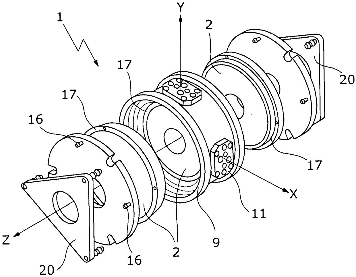
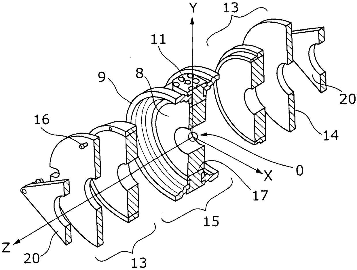
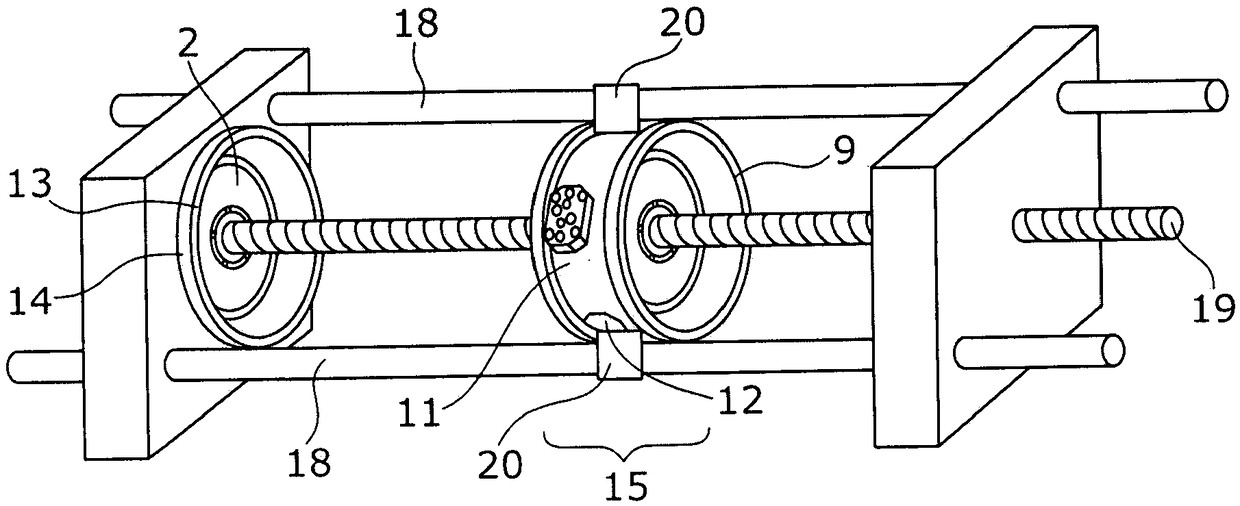
[0077] As shown schematically in different embodiments in the representation of the figures, the main use of the magnet arrangement 1 according to the invention is as a component of a magnetic resonance system not specifically shown in the figures, so The magnetic resonance apparatus has a permanent magnet system, and the magnet arrangement is used in (in Figure 1b A uniform magnetic field is generated in the measurement space 0 shown in ) in the direction of the z-axis, the permanent magnet system has at least two, in particular at least three ring-shaped magnet elements 2, which are arranged cylindrically symmetrically with respect to the z-axis and Arranged one above the other and / or concentrically in the z-direction, the ring magnet elements are made of magnetic material, the ring magnet elements 2 consist of individual magnet segments 3 and are arranged such that each individual segment in the corresponding ring The magnetization direction of the magnetization extends su...


PUM


Abstract

A magnet arrangement (1) having a permanent magnet system with at least two ring-shaped magnet elements (2) which are made of individual magnet segments (3), are arranged cylindrically symmetrically and stacked on one another in the z direction and / or concentrically, and arranged such that the magnetization directions of the individual segments in the rings extend parallel in an x-y plane. The magnet elements align relative to one another in the z direction and have a Halbach magnetization Before final mounting in the magnetic resonance apparatus, the magnet elements are prefabricated as solidstructures and their respective magnet segments are fixed undisplaceably relative to one another. But the magnet elements are displaceable relative to one another in the x-y plane, and are mounted rotatably and / or tiltably relative to one another. Therefore, simple mounting can be performed obviously and furthermore an MR device with a pluralty of Halbach configuration s can be more obviously andmore economically manufactured. Furthermore a magnetic field gradient caused by assembling can be minimized. In other words, a Halbach configuration is presented, and the Halbach configuration structure can operate in an obviously lowered mechanical shimming freedom.

Description

technical field [0001] The invention relates to a magnet arrangement in a magnetic resonance system having a permanent magnet system for generating a homogeneous magnetic field in a measurement space in a direction perpendicular to the z-axis, the permanent magnet system The magnet system comprises at least two, in particular 3, arranged cylindrically symmetrically about the z-axis and arranged one above the other and / or concentrically in the z-direction, said ring-shaped magnet elements being made of magnetic material, said ring-shaped magnet elements being made of a single magnet The segments are formed and arranged such that the magnetization directions of the individual segments in the corresponding ring run substantially parallel in the x-y plane perpendicular to the z direction, the ring magnet elements each have a Halbach magnetization structure, the Halbach The magnetization structure generates a dipolar magnetic field, and each said ring magnet element can be aligned ...

Claims


Application Information

Patent Timeline
IPC IPC(8): G01R33/38G01R33/383H01F7/02
CPCG01R33/3802G01R33/383H01F7/0284G01R33/3873G01N24/08G01R33/307H01F7/0278
Inventor V·尼曼R·皮蒂格L·黑尼肯
Owner BRUKER BIOSPIN
Learn More