
Striking-off device for two sides of ditch for water conservation

A water ditch and water conservancy technology, which is applied to the field of leveling devices on both sides of water utilization drains, can solve the problems of insufficient uniform force and slow leveling speed.

Inactive Publication Date: 2018-11-02
李风花
View PDF6 Cites 4 Cited by
  • Summary
  • Abstract
  • Description
  • Claims
  • Application Information

AI Technical Summary

Problems solved by technology

[0004] In order to overcome the shortcomings of insufficient uniformity and slow speed of scraping the two sides of the ditch manually when pouring the ditch, the technical problem of the present invention is to provide a cement scraper for the two sides of the ditch. Usually, the force is relatively uniform and the speed of scraping is fast. Use the scraping device on both sides of the ditch.

Method used


Image

  • Striking-off device for two sides of ditch for water conservation
  • Striking-off device for two sides of ditch for water conservation
  • Striking-off device for two sides of ditch for water conservation

Examples


Embodiment 1

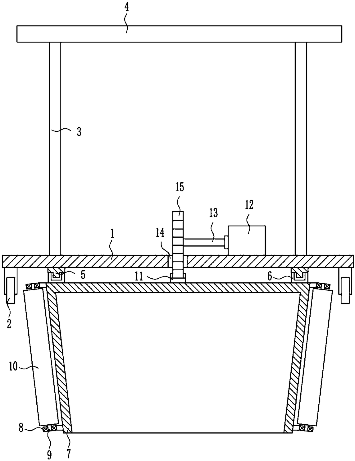
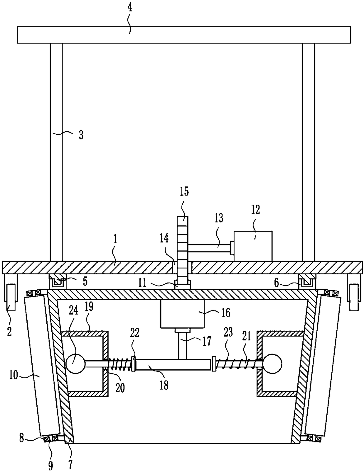
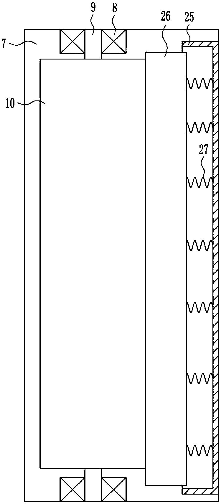
[0021] A water-utilizing device for leveling both sides of the ditch, such as Figure 1-4 As shown, it includes a bottom plate 1, a wheel 2, a vertical rod 3, a grip rod 4, a first slide rail 5, a first slider 6, a frame body 7, a first bearing seat 8, a first rotating shaft 9, a roller 10, and teeth Strip 11, first motor 12, second shaft 13 and gear 15, wheels 2 are installed at the bottom four corners of bottom plate 1, vertical rods 3 are installed on the top left and right sides of bottom plate 1, and grip rods 4 are installed at the top of vertical rod 3. The bottom of the bottom plate 1 is equipped with first slide rails 5 on the left and right sides. The first slide rails 5 are slidably provided with first sliders 6, and the bottoms of the two first sliders 6 are installed with frame bodies 7, frame bodies 7 The upper and lower sides of the left side are equipped with first bearing seats 8, the bearings in the two first bearing seats 8 are connected with the first rotati...

Embodiment 2

[0023] A water-utilizing device for leveling both sides of the ditch, such as Figure 1-4 As shown, it includes a bottom plate 1, a wheel 2, a vertical rod 3, a grip rod 4, a first slide rail 5, a first slider 6, a frame body 7, a first bearing seat 8, a first rotating shaft 9, a roller 10, and teeth Strip 11, first motor 12, second shaft 13 and gear 15, wheels 2 are installed at the bottom four corners of bottom plate 1, vertical rods 3 are installed on the top left and right sides of bottom plate 1, and grip rods 4 are installed at the top of vertical rod 3. The bottom of the bottom plate 1 is equipped with first slide rails 5 on the left and right sides. The first slide rails 5 are slidably provided with first sliders 6, and the bottoms of the two first sliders 6 are installed with frame bodies 7, frame bodies 7 The upper and lower sides of the left side are equipped with first bearing seats 8, the bearings in the two first bearing seats 8 are connected with the first rotati...

Embodiment 3

[0026] A water-utilizing device for leveling both sides of the ditch, such as Figure 1-4 As shown, it includes a bottom plate 1, a wheel 2, a vertical rod 3, a grip rod 4, a first slide rail 5, a first slider 6, a frame body 7, a first bearing seat 8, a first rotating shaft 9, a roller 10, and teeth Strip 11, first motor 12, second shaft 13 and gear 15, wheels 2 are installed at the bottom four corners of bottom plate 1, vertical rods 3 are installed on the top left and right sides of bottom plate 1, and grip rods 4 are installed at the top of vertical rod 3. The bottom of the bottom plate 1 is equipped with first slide rails 5 on the left and right sides. The first slide rails 5 are slidably provided with first sliders 6, and the bottoms of the two first sliders 6 are installed with frame bodies 7, frame bodies 7 The upper and lower sides of the left side are equipped with first bearing seats 8, the bearings in the two first bearing seats 8 are connected with the first rotati...


PUM


Abstract

The invention relates to a striking-off device, in particular to a striking-off device for the two sides of a ditch for water conservation. According to the striking-off device for the two sides of the ditch for water conservation, the force intensity is uniform when cement on the two side faces of the ditch is struck off, and the striking-off speed is high. The striking-off device for the two sides of the ditch for water conservation comprises a bottom plate, wheels, vertical rods, a holding rod, first sliding rails, first sliding blocks, a frame body and the like. The wheels are mounted at the four corners of the bottom of the bottom plate correspondingly. The vertical rods are mounted on the left side and the right side of the top of the bottom plate correspondingly. The holding rod ismounted at the top ends of the vertical rods. The first sliding rails are mounted on the left side and the right side of the bottom of the bottom plate correspondingly. According to the striking-off device for the two sides of the ditch for water conservation, the frame body is driven by a first motor to move forwards and backwards continuously, and thus the frame body can drive a roller to strikeoff the cement on the two side faces in the ditch; and a beating hammer is driven by a second motor to beat the frame body, thus the cement can be more compact, and accordingly, the effects that theforce intensity is uniform when the cement on the two side faces of the ditch is struck off, and the striking-off speed is high are achieved.

Description

Technical field [0001] The invention relates to a leveling device, in particular to a leveling device on both sides of a water utilization ditch. Background technique [0002] A water conservancy project is a project built for the purpose of controlling and arranging surface water and groundwater in the natural world to achieve the purpose of eliminating harm and benefiting. Also called water engineering. Water is a precious resource indispensable for human production and life, but its natural state does not fully meet human needs. Only by building water conservancy projects can we control water flow, prevent floods, and regulate and distribute water volume to meet the needs of people for water resources in life and production. Water conservancy projects need to build different types of hydraulic structures such as dams, dikes, spillways, sluices, water inlets, channels, ferry channels, raft channels, and fish channels to achieve their goals. [0003] In order to make rural padd...

Claims


Application Information

Patent Timeline
Patent Type & Authority Applications(China)
IPC IPC(8): E02B5/02E02D15/00
CPCE02B5/02E02D15/00
Inventor 李风花陈涛季莹
Owner 李风花
Learn More