
A negative pressure compact spinning device

A negative pressure, agglomeration roller technology, used in spinning machines, textiles and papermaking, drafting equipment, etc., can solve the problems of easy accumulation of flowers in spring gaps, large frictional resistance, and reduced service life, reducing yarn hairiness, The effect of improving single yarn strength and reducing service life

Pending Publication Date: 2018-11-02
江阴市华方新技术科研有限公司
View PDF3 Cites 2 Cited by
  • Summary
  • Abstract
  • Description
  • Claims
  • Application Information

AI Technical Summary

Problems solved by technology

[0003] In the existing negative pressure accumulation devices, most of the mesh rings are tensioned by spring tension mechanisms to ensure that the mesh rings are always tightly covered on the upper part of the accumulation tank. The springs used are divided into coil springs and torsion springs. The tension mechanism of this kind of spring has a relatively complicated structure, and it is easy to accumulate flowers in the spring gap, and it is very inconvenient to disassemble; and because the mesh ring is always in a tensioned state during the spinning process, the friction between the mesh ring and the tension device The resistance is large, which greatly reduces the service life; the mesh ring is in close contact with the yarn during operation, and it is easy to accumulate flying flowers and dust in the space formed by the collecting tube, mesh ring and tension mechanism, and these flying flowers and dust are not easy Cross over the tensioning high point of the tension mechanism, and it is easy to produce flower accumulation at this position. When there is a lot of flower accumulation, the rotation speed of the grid ring will be reduced, thereby affecting the yarn hairiness index and yarn strength
When there are too many accumulated flowers, the grid circle will run out of the control range of the tension support, causing the grid circle to deviate, which will cause more serious quality problems

Method used


Image

  • A negative pressure compact spinning device
  • A negative pressure compact spinning device
  • A negative pressure compact spinning device

Examples


Embodiment Construction

[0063] The present invention will be further described in detail below in conjunction with the accompanying drawings and embodiments.

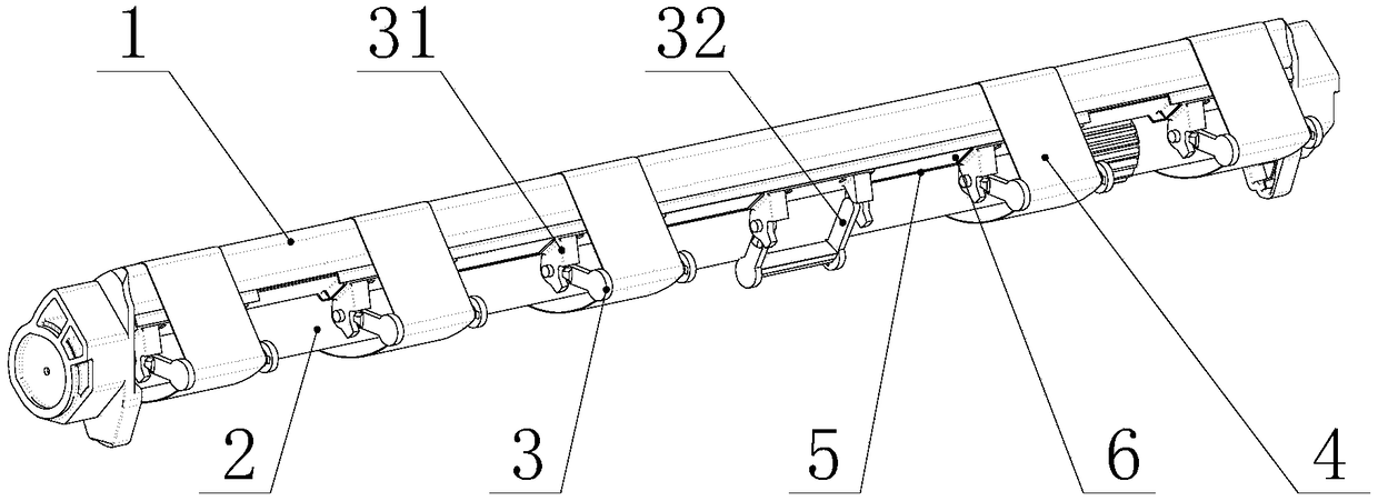
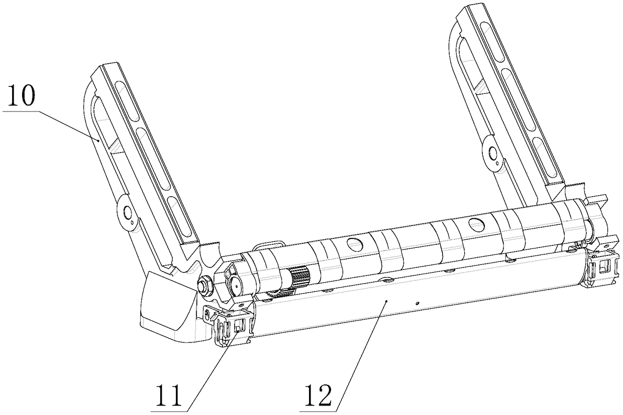
[0064] Such as Figure 1 to Figure 11As shown, a negative pressure compact spinning device in this embodiment includes a special-shaped tube 1 and a gathering roller 2. A plurality of supporting mechanisms 3 are arranged on the lower side of the special-shaped tube 1. The special-shaped tube 1 and the compacting roller A mesh ring 4 is loosely fitted between 2 and the supporting mechanism 3;

[0065] The perimeter of the grid ring 4 is slightly greater than the outer envelope (surrounding) length between the special-shaped pipe 1, the accumulation roller 2 and the support mechanism 3;

[0066] The perimeter of the mesh ring 4 is 1-3mm larger than the outer envelope (surrounding) length between the special-shaped pipe 1, the accumulation roller 2 and the support mechanism 3, and the best size is 2mm greater than its outer envelope length;

[...


PUM


Abstract

The invention relates to a negative pressure compact spinning device. The device includes a special pipe (1) and a compacting roller (2); the lower side of the special pipe (1) is provided with multiple support mechanisms (3); the special pipe (1), the compacting roller (2) and the multiple support mechanisms (3) are loosely sleeved by grid loops (4), and the perimeter of the grid loops is slightly higher than the envelope length of the special pipe (1), the compacting roller (2) and the multiple support mechanisms (3). A traditional grid loop tension force support mechanism is replaced by adopting fix support mechanisms; the special pipe (1), the compacting roller (2) and the multiple support mechanisms (3) are loosely sleeved by the grid loops (4), so that accumulating flying cotton generated on the inner side surfaces of the grid loops (4) pass the high point positions of the support mechanisms easily, the accumulating flying cotton moves to the position of a compacting groove of the special pipe and can be sucked away in time, and the grid loops can maintain flexible rotation; the accumulating flying cotton of the compact spinning device are effectively reduced, the cleaning period of spinning is greatly prolonged, and the yarn hairiness index and yarn strength are guaranteed.

Description

technical field [0001] The invention relates to a negative pressure compact spinning device, which belongs to the technical field of spinning machinery. Background technique [0002] The compact spinning frame is to add a concentrating device in front of the front roller of the original spinning frame. By concentrating the fiber bundles, the purpose of reducing yarn hairiness and improving the strength of single yarn is achieved. tensioning device and other components. There is a collecting groove on one side of the collecting pipe, and a mesh ring is arranged on the upper part of the groove, and the mesh ring is driven by the transmission device to make a rotary motion to transport the drawn fiber forward. The suction port joint on the collecting pipe is connected with the suction pipe, and the negative pressure generated by the suction fan generates suction at the notch of the collecting pipe, and gathers the fibers through the mesh ring, thereby reducing yarn hairiness. ...

Claims


Application Information

Patent Timeline
Patent Type & Authority Applications(China)
IPC IPC(8): D01H5/66D01H5/72
CPCD01H5/66D01H5/72Y02P70/62
Inventor 吴奕宏胡文君闫中旭陆荣海沈杰
Owner 江阴市华方新技术科研有限公司
Learn More