Device for converting blood collection tubes in lateral motion into vertically oriented motion

A technology of lateral movement and directional movement, which is applied in the field of medical devices, can solve the problems of uncertain barcode direction of blood collection tubes, failure of automatic classification of blood collection tubes, lack of directional function, etc., and achieves short transmission distance, flexible and convenient use, and small size Effect

Active Publication Date: 2020-02-14
合肥妙思智能医疗科技有限公司
View PDF7 Cites 0 Cited by
  • Summary
  • Abstract
  • Description
  • Claims
  • Application Information

AI Technical Summary

Problems solved by technology

[0002] Hospitals usually use manual processing to scan and sort blood collection tubes, which requires a lot of labor costs
However, the intelligent blood collection system cannot automatically classify various types of blood collection tubes, and different blood collection tubes need to use different blood collection systems, which will cause a large waste of resources and complicate the blood collection system.
At present, the existing scanning sorting does not have the orientation function, and the direction of the barcode on the test tube is uncertain after the scanned blood collection tube is transported by the conveyor belt.

Method used


Image

  • Device for converting blood collection tubes in lateral motion into vertically oriented motion
  • Device for converting blood collection tubes in lateral motion into vertically oriented motion
  • Device for converting blood collection tubes in lateral motion into vertically oriented motion

Examples


Embodiment Construction

[0027] The following will clearly and completely describe the technical solutions in the embodiments of the present invention with reference to the accompanying drawings in the embodiments of the present invention. Obviously, the described embodiments are only some, not all, embodiments of the present invention. Based on the embodiments of the present invention, all other embodiments obtained by persons of ordinary skill in the art without creative efforts fall within the protection scope of the present invention.

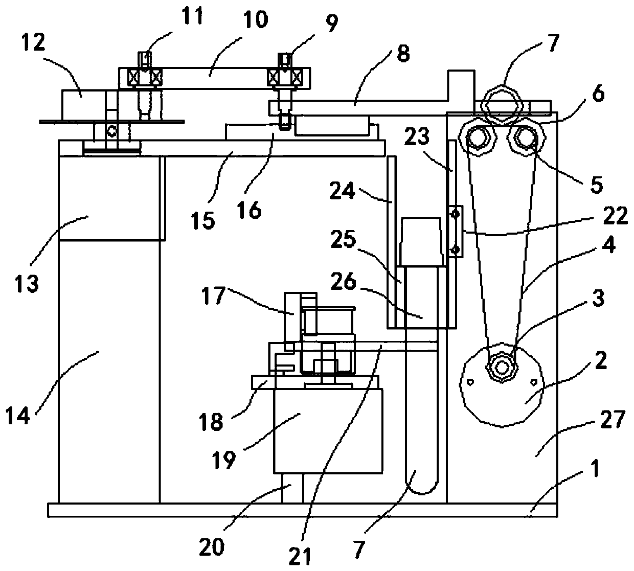
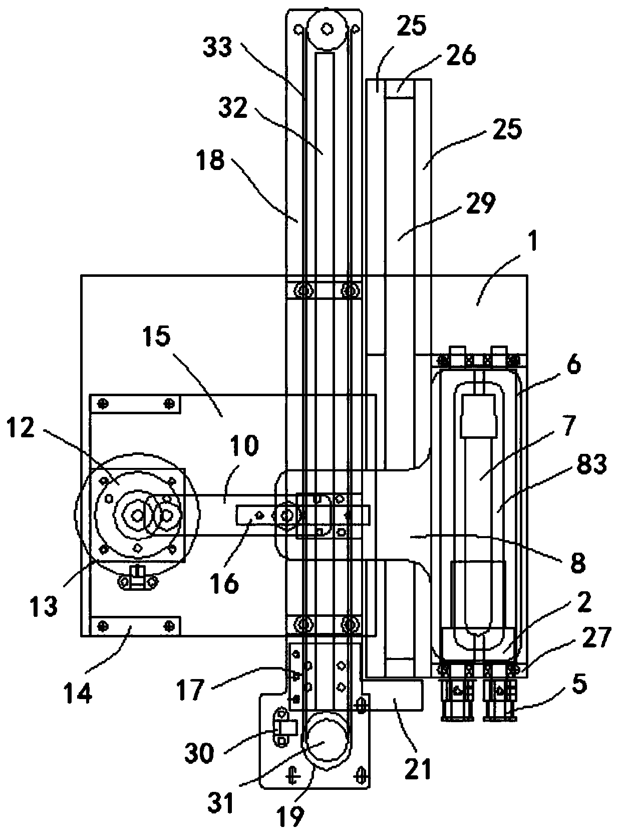
[0028] Such as Figure 1-2 A device for converting a blood collection tube in lateral motion into a vertically oriented motion is shown, including a base plate 1 and two first support plates 27 and two second support plates 14 vertically arranged on the base plate 1;

[0029] The two first support plates 27 are oppositely arranged, and two rubber rollers 6 arranged horizontally opposite to each other are movably installed on the upper part of them through bearings....


PUM


Abstract

The invention discloses a device for converting transverse movement of a blood collection tube into vertical directional movement. The device comprises a bottom plate, two first supporting plates andtwo second supporting plates, wherein the two first supporting plates and the two second supporting plates are vertically arranged on the bottom plate. The two first supporting plates are oppositely arranged, two rubber rollers oppositely arranged in the horizontal direction are movably installed on the upper portions of the two first supporting plates through bearings, the same ends of the two rubber rollers penetrate through the first supporting plate on one side and are provided with driven wheels, the driven wheels on the two rubber rollers are connected with a driving wheel installed on an output shaft of a first motor through a conveying belt, and the first motor is installed on the first supporting plate on the corresponding side. The inner sides of the two second supporting platesare each connected with a fixed block through bolts, a first baffle is installed between the two fixed blocks, and a directional bearing mechanism is installed on the outer side of the lower portion of the first baffle. The device greatly improves blood collection efficiency, is small in size, short in conveying distance, flexible and convenient to use and high in working efficiency, and providesgreat convenience for subsequent transferring, distributing, marking and management work of the blood collection tube.

Description

technical field [0001] The invention belongs to the technical field of medical instruments, and in particular relates to a device for converting a blood collection tube in lateral motion into vertical orientation motion. Background technique [0002] Hospitals usually use manual processing to scan and sort blood collection tubes, which requires a lot of labor costs. However, the intelligent blood collection system cannot automatically classify various types of blood collection tubes, and different blood collection tubes need to use different blood collection systems, which will cause a large waste of resources and complicate the blood collection system. At present, the existing scanning sorting does not have the orientation function, and the direction of the barcode on the test tube is uncertain after the scanned blood collection tube is transported by the conveyor belt. In order to realize the vertical orientation function of the blood collection tube after scanning the co...

Claims


Application Information

Patent Timeline
Patent Type & Authority Patents(China)
IPC IPC(8): B65G47/24B65G13/07B65G47/74
CPCB65G13/07B65G47/24B65G47/74B65G2201/0276
Inventor 李进华
Owner 合肥妙思智能医疗科技有限公司
Why Eureka
Try Eureka