Eureka AIR delivers breakthrough ideas for toughest innovation challenges, trusted by R&D personnel around the world.

Manufacturing method for spiral twisted box type

A production method and spiral technology are applied in the production field of spiral twisted box shapes, which can solve the problems of high production requirements, low production efficiency, and difficult installation, and achieve the effects of ensuring production quality, improving production efficiency, and meeting assembly precision requirements.

Active Publication Date: 2018-11-02
二十二冶集团装备制造有限公司
View PDF8 Cites 8 Cited by
  • Summary
  • Abstract
  • Description
  • Claims
  • Application Information

AI Technical Summary

Problems solved by technology

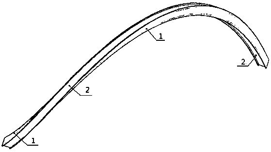
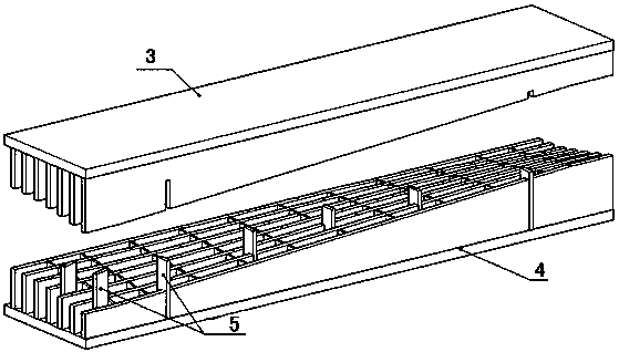
[0002] The roof structure of the pedestrian bridge adopts a time-space spiral structure with a unique shape. The main keel of the roof is composed of 27 space-distorted box shapes. The main keel is twisted to a large extent. The main part of the cover main keel is a space-time spiral twisted box. The space-time spiral twisted box is composed of upper flange plate, lower flange plate, webs on both sides and inner partitions. The whole component is in a space-time spiral twisted shape. When the main keel is docked and installed, the production of the spiral twisted box requires high precision. The space-time spiral twisted box is quite different from the ordinary box structure in columns, beams, and trusses. The existing production and processing of the space-time spiral twisted box method, cannot meet the assembly accuracy requirements, the production efficiency is low, and the quality of the space-time spiral twisted box produced is poor, and it is often difficult or impossible to install due to dimensional accuracy problems

Method used


Image

  • Manufacturing method for spiral twisted box type
  • Manufacturing method for spiral twisted box type
  • Manufacturing method for spiral twisted box type

Examples


Embodiment Construction

[0034] The present invention will be further described below in conjunction with the examples, the purpose is only to better understand the contents of the present invention, therefore, the examples given do not limit the protection scope of the present invention.

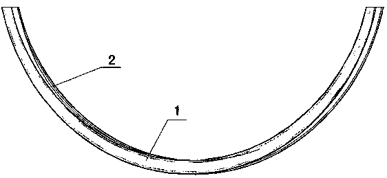
[0035] see figure 1 , one A manufacturing method of a spiral twisted box type is carried out according to the following steps:

[0036] Step 1: With the aid of CAD, Tekla Structures and other 3D drawing software, establish models of all helically twisted box-shaped members of the whole bridge, and classify and number all helically twisted box-shaped structural members of the whole bridge. The edge plate 1 and the web plate 2 are unfolded respectively.

[0037] Step 2, according to the capacity of the processing equipment, the expanded flange plate 1 and web plate 2 are cut into sections, and the length of the sections is equally divided to ensure the versatility of the flange plate and web plate, and each sectio...


PUM


Abstract

The invention relates to a manufacturing method for a spiral twisted box type. The method comprises that the entire engineering model diagram is drawn, the same components are classified, flange plates and web plates of the different members are respectively extended and sampled, the extended flange plates and web plates are discharged in a segmented mode, the upper and lower flange plates are hot-pressed and molded by using a die made according to the box-type member twisted shape size, the web plates are rolled by using a plate rolling machine, an shape-imitation assembly tread is made according to the different members, the segmented pressed-molded flange plates are placed on the special assembly tread for splicing, welding, repairing so as to be tightly attach to the tread, and then the web plates and internal partition plates are assembled; and the internal partition plates are welded, the assembly accuracy is controlled by the assembly tread and the fit gap of the tread, the boxflange plates and the web plates, finally, the additional flange plates are assembled, and by combining with the trimming, the assembly detecting, welding of the box type main seam, post-welding detecting, member rust removal, and member coating are conducted. By means of the manufacturing method, the production efficiency can be improved, the production quality is ensured, and the requirements ofthe assembly accuracy are met.

Description

technical field [0001] The invention relates to a manufacturing method of a steel structure box-shaped member, in particular to a manufacturing method of a spiral twisted box-shaped member. Background technique [0002] The roof structure of the pedestrian bridge adopts a space-time spiral structure with a unique shape. The main keel of the roof is composed of 27 space-distorted box shapes. The main keel is twisted to a large extent. The main part of the cover main keel is a space-time spiral twisted box. The space-time spiral twisted box is composed of an upper flange plate, a lower flange plate, webs on both sides, and inner partitions. When the main keel is docked and installed, the production of the spiral twisted box requires high precision. The space-time spiral twisted box is quite different from the ordinary box structure such as columns, beams, and trusses. The existing production and processing of the space-time spiral twisted box method, cannot meet the assembly ...

Claims


Application Information

Patent Timeline
IPC IPC(8): B23K31/02B23K37/00
CPCB23K31/02B23K37/00
Inventor 杨彬颜世强王夺
Owner 二十二冶集团装备制造有限公司
Why Eureka
Eureka Blog
Learn More