
Specially-shaped plate crossbeam bridge steel spring supporting and jacking active reinforcing construction method

A technology of steel springs and special-shaped plates, which is applied in the field of active reinforcement construction method of steel spring abutments of bridge beams with special-shaped plates, can solve the problems of insufficient shear resistance and potential safety hazards of the middle beams, and achieve the effect of strengthening quality and ensuring reinforcement

Active Publication Date: 2018-10-26
CHINA RAILWAY CONSTR BRIDGE ENG BUREAU GRP
View PDF5 Cites 4 Cited by
  • Summary
  • Abstract
  • Description
  • Claims
  • Application Information

AI Technical Summary

Problems solved by technology

[0002] The crossbeam area of ​​the special-shaped slab of the overpass is a concrete integral cast-in-place special-shaped structure. Due to the different degrees of settlement of the pile foundation, the shear resistance of the middle beam is insufficient, and there are potential safety hazards

Method used


Image

  • Specially-shaped plate crossbeam bridge steel spring supporting and jacking active reinforcing construction method
  • Specially-shaped plate crossbeam bridge steel spring supporting and jacking active reinforcing construction method
  • Specially-shaped plate crossbeam bridge steel spring supporting and jacking active reinforcing construction method

Examples


Embodiment 1

[0047] A construction method for actively reinforcing steel spring abutments of special-shaped plate beam bridges, mainly including the following steps:

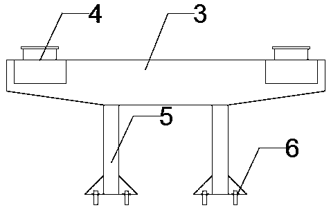
[0048] Step S101: First, add π-shaped steel cap beams 3 on both sides of the pier column 2;

[0049] Step S102: Then set a force-measuring adjustable pot-type rubber bearing 4 at both ends of the π-shaped steel cover beam 3;

[0050] Step S103: Finally, use the synchronous hydraulic jacking system to support the beam and the π-shaped steel cover beam 3, so that the π-shaped steel cover beam 3 produces elastic deformation; when the stress and strain on the π-shaped steel cover beam 3 reach the standard, adjust The force-measuring adjustable basin-type rubber bearing 4 makes the upper and lower sides of the force-measuring adjustable basin-type rubber bearing 4 closely adhere to the middle beam 1 and the π-shaped steel cover beam 3 respectively, and the force-measuring adjustable basin-type rubber bearing 4 is locked, and aft...

Embodiment 2

[0052] This embodiment is further optimized on the basis of Embodiment 1. Before the construction, it also includes step A. The step A includes the following steps: excavate the periphery of the pier column 2, and expose the top surface of the cap; the pier column 2. The periphery of the platform cap is hardened with C20 concrete, and the thickness is 20cm to ensure the flatness of the base; the top surface of the platform is leveled with 2 cm thick 60MPa epoxy mortar. Through the operation of the step A, the present invention ensures the flatness of the bearing platform and the smooth progress of the follow-up work.

[0053] Other parts of this embodiment are the same as those of Embodiment 1, so details are not repeated here.

Embodiment 3

[0055] This embodiment is further optimized on the basis of embodiment 2, as Figure 1-Figure 5 As shown, the step S101 mainly includes the following steps:

[0056] Step S1011: Before installing the π-shaped steel cover beam 3, drill anchor bolt holes on the top surface of the bearing platform 7 in advance, and the drill holes are drilled with water drills, and the hole diameter is 35mm; Platform 7, anchor bolt model M30, length 80cm;

[0057] Step S1012: Assembling the π-shaped steel cover beam 3 is about to assemble the parts that are divided into four sections in the factory, that is, the two sections of beams on the upper part of the π-shaped steel cover beam 3 and the two steel piers 5 below. The two beams on the upper part of the shaped steel cover beam 3 are butted, and the pier column 2 is wrapped in the middle, and welded after alignment. After the welding is completed, the two steel pier columns 2 are placed on the π-shaped steel cover beam 3 respectively On the l...


PUM


Abstract

The invention discloses a specially-shaped plate crossbeam bridge steel spring supporting and jacking active reinforcing construction method. The method includes the steps that S101, an n-shaped steelbent cap is additionally arranged on the two sides of a first pier column; S102, the two ends on the n-shaped steel bent cap are each provided with a force measurement adjustable basin type rubber support; and S103, a synchronous hydraulic jacking system is adopted for supporting and jacking a crossbeam and the n-shaped steel bent cap, and the n-shaped steel bent cap elastically deforms; and theforce measurement adjustable basin type rubber supports are adjusted, so that the upper portions and the lower portions of the force measurement adjustable basin type rubber supports are tightly attached to the middle crossbeam and the n-shaped steel bent cap, the force measurement adjustable basin type rubber supports are locked, and supporting and jacking force can be transmitted to the middle crossbeam through the force measurement adjustable basin type rubber supports. A single-point supporting structure of an original bridge is converted into a three-point supporting structure through steel spring supporting and jacking, the shear force and the pressure borne by the pier column are jointly borne through three positions, the problem that the middle crossbeam is insufficient in shear capacity is solved, the service life of a bridge is prolonged, and the safety of the bridge is guaranteed.

Description

technical field [0001] The invention belongs to the technical field of reinforcement construction of special-shaped slab beams of overpass bridges, and in particular relates to an active reinforcement construction method for special-shaped slab beam bridge steel spring abutment tops. Background technique [0002] The special-shaped slab beam area of ​​the overpass bridge is a concrete integral cast-in-place special-shaped structure. Due to the different degrees of settlement of the pile foundation, the shear resistance of the middle beam is insufficient, and there are potential safety hazards. In view of the fact that the special-shaped slab beam of this bridge is a large-scale single-point support special-shaped slab beam bridge, the structural force is complex, and it is sensitive to uneven settlement. In order to strengthen it, the reinforcement method of steel spring abutment was first adopted to avoid the pile foundation. During the settlement, the center beam is subjec...

Claims


Application Information

Patent Timeline
Patent Type & Authority Applications(China)
IPC IPC(8): E01D22/00
CPCE01D22/00
Inventor 苏春生何十美张庆孙百峰
Owner CHINA RAILWAY CONSTR BRIDGE ENG BUREAU GRP
Learn More